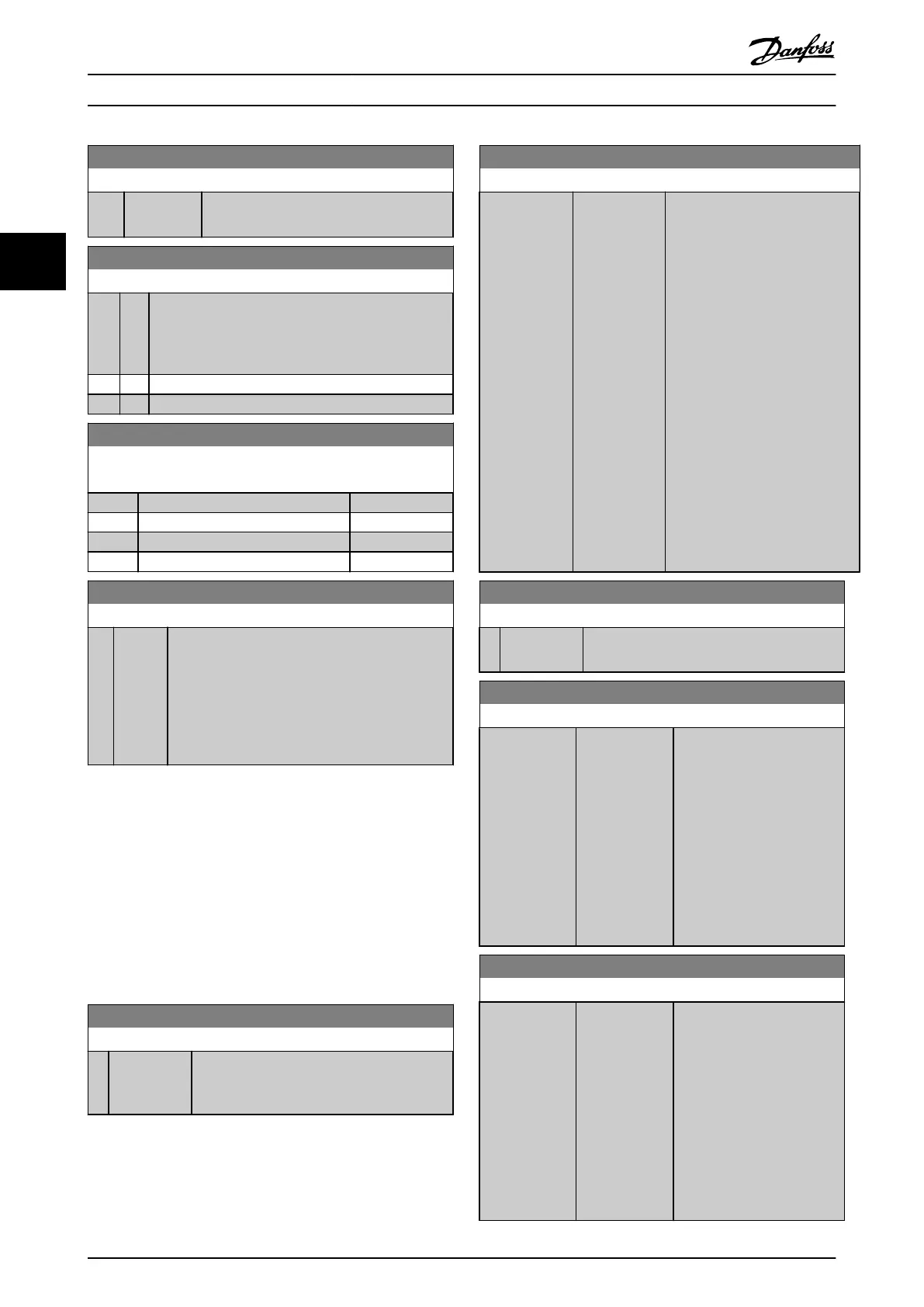
16-39 Control Card Temp.
Range: Function:
0 °C* [0 - 100 °C] View the temperature on the control card,
stated in °C.
16-40 Logging Buer Full
Option: Function:
View whether the logging buer is full (see parameter
group 15-1* Data Log Settings). The logging buer is
never full when parameter 15-13 Logging Mode is set
to [0] Log always.
[0] * No
[1] Yes
16-43 Timed Actions Status
View the timed actions mode.
Option: Function:
[0] * Timed Actions Auto
[1] Timed Actions Disabled
[2] Constant On Actions
[3] Constant O Actions
16-49 Current Fault Source
Range: Function:
0* [0 - 8 ] The Value indicates source of current fault,
including:
•
Short circuit.
•
Overcurrent
•
Pase imbalance (from left): [1-4] Inverter,
[5-8] Rectier, [0] No fault recorded.
After a short-circuit alarm (I
max2
) or overcurrent alarm (I
max1
or phase imbalance), this contains the power card number
associated with the alarm. It only holds 1 number
indicating the highest priority power card number (master
rst). The value persists on power cycle, but if a new alarm
occurs it is overwritten by the new power card number
(even if it is a lower priority number). The value is only
cleared when the alarm log is cleared (that is a 3-nger
reset would reset the readout to 0).
3.16.4
16-5* Ref. & Feedb.
16-50 External Reference
Range: Function:
0* [-200 - 200 ] View the total reference, the sum of digital,
analog, preset, bus and freeze references, plus
catch-up and slow-down.
16-52 Feedback[Unit]
Range: Function:
0
ProcessCtrlUnit*
[-999999.999
- 999999.999
ProcessCtrlUnit]
View value of resulting feedback
value after processing of feedback
1-3 see
•
Parameter 16-54 Feedback
1 [Unit].
•
Parameter 16-55 Feedback
2 [Unit].
•
Parameter 16-56 Feedback
3 [Unit].
in the feedback manager.
See parameter group 20-0*
Feedback.
The value is limited by settings in
parameter 20-13 Minimum
Reference/Feedb., and
parameter 20-14 Maximum
Reference/Feedb. Units as set in
20-12 Reference/Feedback Unit.
16-53 Digi Pot Reference
Range: Function:
0* [-200 - 200 ] View the contribution of the digital potenti-
ometer to the actual reference.
16-54 Feedback 1 [Unit]
Range: Function:
0
ProcessCtrlUnit*
[-999999.999 -
999999.999
ProcessCtrlUnit]
View value of Feedback 1, see
parameter group 20-0*
Feedback.
The value is limited by
settings in
parameter 20-13 Minimum
Reference/Feedb. and
parameter 20-14 Maximum
Reference/Feedb.. Units as set
in 20-12 Reference/Feedback
Unit.
16-55 Feedback 2 [Unit]
Range: Function:
0
ProcessCtrlUnit*
[-999999.999 -
999999.999
ProcessCtrlUnit]
View value of feedback 2, see
parameter group 20-0*
Feedback.
The value is limited by
settings in
parameter 20-13 Minimum
Reference/Feedb. and
parameter 20-14 Maximum
Reference/Feedb. Units as set
in 20-12 Reference/Feedback
Unit.
Parameter Descriptions
VLT
®
HVAC Drive FC 102
132 Danfoss A/S © 03/2015 All rights reserved. MG11CE02
33
 Loading...


