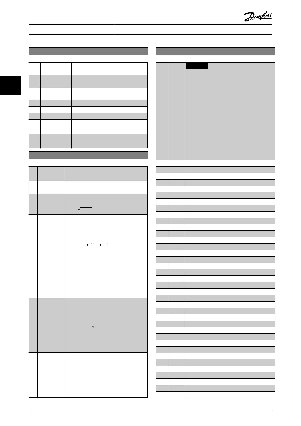
20-00 Feedback 1 Source
Option: Function:
[10] Analog Input
X42/3
[11] Analog Input
X42/5
[15] Analog Input
X48/2
[100] Bus Feedback 1
[101] Bus Feedback 2
[102] Bus feedback 3
[104] Sensorless Flow Requires set-up by MCT 10 Set-up
Software with sensorless-specic plug-in.
[105] Sensorless
Pressure
Requires set-up by MCT 10 Set-up
Software with sensorless-specic plug-in.
20-01 Feedback 1 Conversion
Option: Function:
This parameter allows a conversion function
to be applied to feedback 1.
[0]
*
Linear No eect on the feedback.
[1] Square root Commonly used when a pressure sensor is
used to provide ow feedback
(( flow ∝ pressure)).
[2] Pressure to
temperature
Used in compressor applications to provide
temperature feedback using a pressure
sensor. The temperature of the refrigerant is
calculated using the following formula:
Temperature =
A2
ln Pe + 1 − A1
− A3,
where A1, A2 and A3 are refrigerant-specic
constants. Select the refrigerant in
parameter 20-30 Refrigerant.
Parameter 20-21 Setpoint 1 through
parameter 20-23 Setpoint 3 allow the values of
A1, A2 and A3 to be entered for a refrigerant
that is not listed in
parameter 20-30 Refrigerant.
[3] Pressure to
ow
Used in applications for controlling the air
ow in a duct. A dynamic pressure
measurement (pitot tube) represents the
feedback signal.
Flow = DuctArea × DynamicPressure
× AirDensityFactor
See also parameter 20-34 Duct 1 Area [m2]
through parameter 20-38 Air Density Factor [%]
for setting of duct area and air density.
[4] Velocity to
ow
Used in applications for controlling the air
ow in a duct. An air velocity measurement
represents the feedback signal.
Flow = DuctArea × AirVelocity
See also parameter 20-34 Duct 1 Area [m2]
through parameter 20-37 Duct 2 Area [in2] for
setting of duct area.
20-02 Feedback 1 Source Unit
Option: Function:
NOTICE
This parameter is only available when
using pressure to temperature feedback
conversion.
If option [0] Linear is selected in
parameter 20-01 Feedback 1 Conversion, the
setting of any option in
parameter 20-02 Feedback 1 Source Unit
does not matter as a conversion is 1-to-1.
This parameter determines the unit that is used
for this feedback source, before applying the
feedback conversion of parameter 20-01 Feedback
1 Conversion. This unit is not used by the PID
controller.
[0] None
[1] %
[5] PPM
[10] 1/min
[11] RPM
[12] Pulse/s
[20] l/s
[21] l/min
[22] l/h
[23] m³/s
[24] m³/min
[25] m³/h
[30] kg/s
[31] kg/min
[32] kg/h
[33] t/min
[34] t/h
[40] m/s
[41] m/min
[45] m
[60] °C
[70] mbar
[71] bar
[72] Pa
[73] kPa
[74] m WG
[75] mm Hg
[80] kW
[120] GPM
[121] gal/s
[122] gal/min
[123] gal/h
[124] CFM
[125] ft³/s
[126] ft³/min
[127] ft³/h
[130] lb/s
Parameter Descriptions
VLT
®
HVAC Drive FC 102
140 Danfoss A/S © 03/2015 All rights reserved. MG11CE02
33
 Loading...


