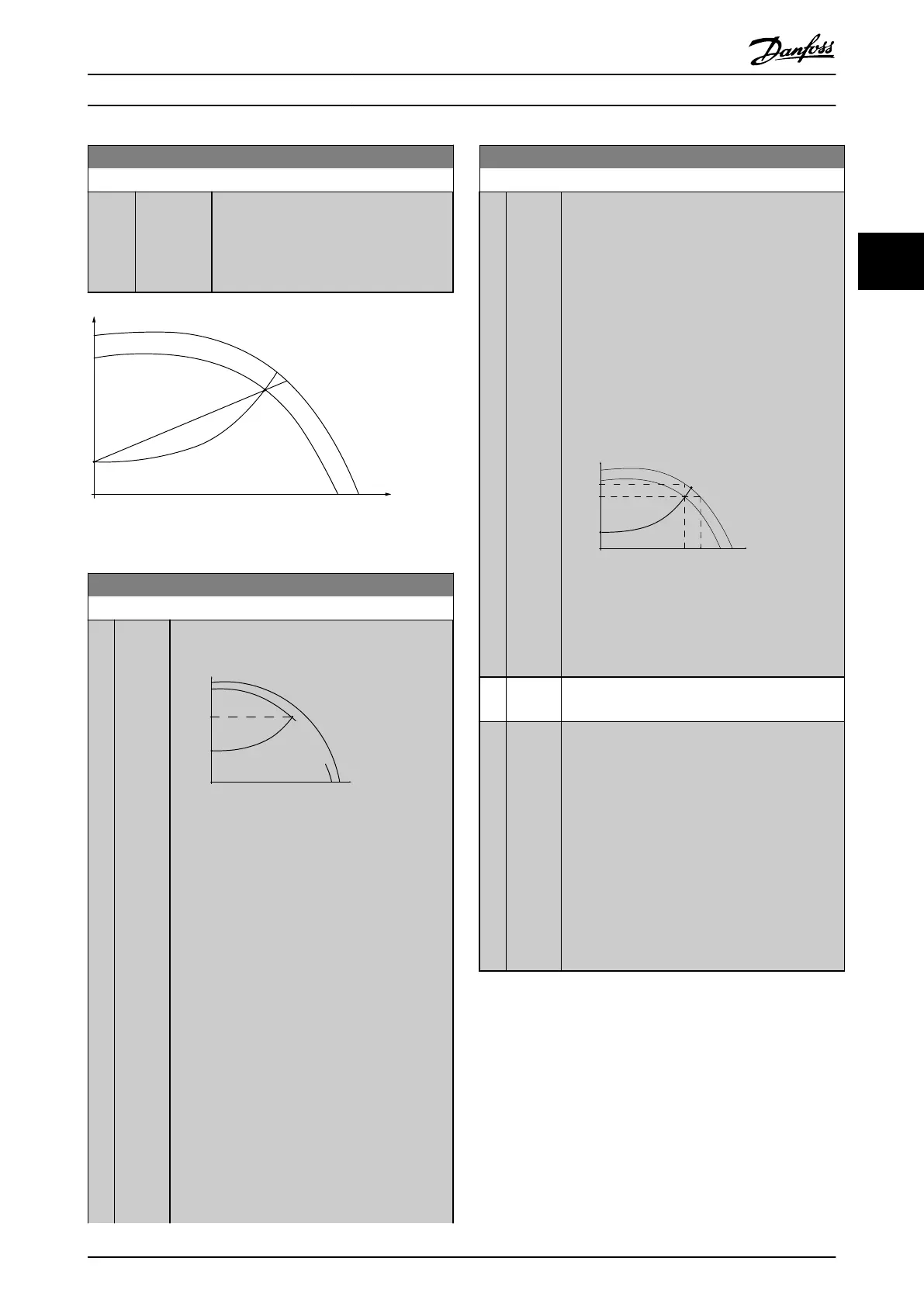
22-81 Square-linear Curve Approximation
Range: Function:
100 %* [0 - 100 %]
Example 1:
Adjustment of this parameter allows the
shape of the control curve to be adjusted.
0=Linear
100%=Ideal shape (theoretical).
Control Curve
(head)
(ow)
H
Q
130BA388.11
100%
P22-81 0%
Illustration 3.57 Square-Linear Curve Approximation
22-82 Work Point Calculation
Option: Function:
Example 1
A
130BA385.11
P22-85/22-86
Control Curve
H
MIN
H
DESIGN
Set Point
n
RATED
_
f
RATED
n
DESIGN
-
f
DESIGN
Q
(flow)
H
(head)
Par.:
22-83/
22-84/
22-87
Illustration 3.58 Speed at System Design
Working Point is Known
From the data sheet showing characteristics for
the specic equipment at dierent speeds, simply
reading across from the H
DESIGN
point and the
Q
DESIGN
point allows
nding point A, which is the
system design working point. The pump character-
istics at this point should be identied and the
associated speed programmed. Closing the valves
and adjusting the speed until H
MIN
has been
achieved allows the speed at the no-ow point to
be identied.
Adjustment of parameter 22-81 Square-linear Curve
Approximation then allows the shape of the
control curve to be adjusted
innitely.
Example 2:
Speed at system design working point is not
known: Where the speed at system design
working point is unknown, another reference point
22-82 Work Point Calculation
Option: Function:
on the control curve needs to be determined
based on the data sheet. By looking at the curve
for the rated speed and plotting the design
pressure (H
DESIGN
, Point C), the ow at that
pressure, Q
RATED
, can be determined. Similarly, by
plotting the design ow (Q
DESIGN
, Point D), the
pressure H
DESIGN
at that ow can be determined.
Knowing these 2 points on the pump curve, along
with H
MIN
as described above, allows the
frequency converter to calculate the reference
point B and thus to plot the control curve, which
also includes the system design working point A.
Set point
Control Curve
n
D
E
S
I
G
N
-
f
D
E
S
I
G
N
n
R
A
T
E
D
-
f
R
A
T
E
D
(head)H
H
RATED
Par.
22-88
Q
DESIGN
Par.
22-89
H
MIN
D
B
C
A
Q
RATED
Par.
22-90
(flow)
Q
H
DESIGN
130BA387.11
22-84/
22-87
22-83/
Par.:
Illustration 3.59 Speed at System Design
Working Point is not Known
[0]
*
Disabled Work point calculation not active. To be used if
speed at design point is known.
[1] Enabled Work point calculation is active. Enabling this
parameter allows the calculation of the unknown
system design working point at 50/60 Hz speed,
from the input data set in
•
Parameter 22-83 Speed at No-Flow [RPM].
•
Parameter 22-84 Speed at No-Flow [Hz].
•
Parameter 22-87 Pressure at No-Flow
Speed.
•
Parameter 22-88 Pressure at Rated Speed.
•
Parameter 22-89 Flow at Design Point.
•
Parameter 22-90 Flow at Rated Speed.
Parameter Descriptions Programming Guide
MG11CE02 Danfoss A/S © 03/2015 All rights reserved. 171
3 3
 Loading...


