22 of 114
M-AP-001-EN Rev. Q
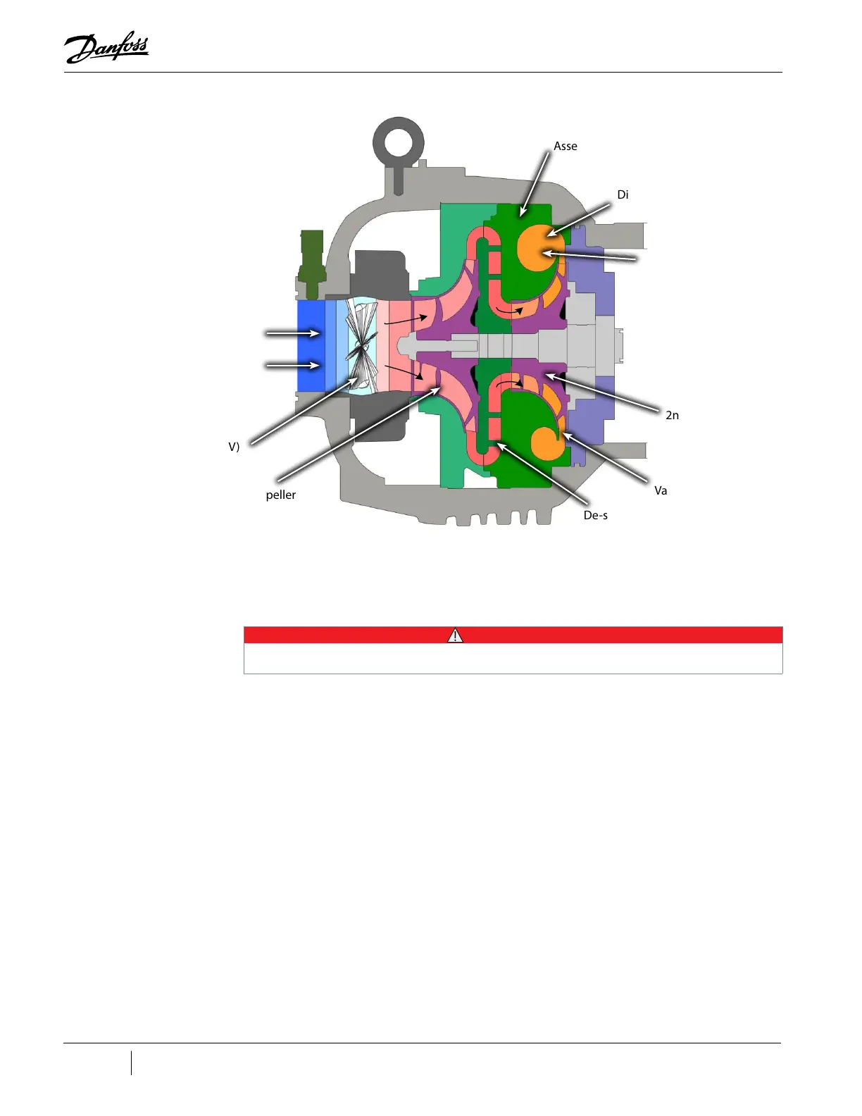
Figure 3-2 Compressor Fluid Path (TGS310, TTS350, TGS390, TGS490, TTS400, TGS520, and TTS700)
3.2 Motor Cooling
Liquid refrigerant is channeled at full condenser pressure from the main liquid line to the compressor
to cool the electronic, mechanical, and electromechanical components (refer to "Figure 3-3
Compressor Cooling Circuit (TGS230 / TTS300)" and "Figure 3-4 Compressor Cooling Circuit (TTS300
Split-Cooling, TGS310, TTS350, TGS390, TGS490, TTS400, TT700, and TGS520)".
• • • CAUTION • • •
A minimum operating pressure ratio of 1.5 is required to maintain adequate cooling of the compressor.
The sub-cooled refrigerant enters the compressor through two solenoid valves and associated fixed
orifices located behind the service access cover. The orifices cause the refrigerant to expand, thereby
lowering its temperature. Both valves open in response to the temperature sensed in the motor and
inverter.
From the outlet of the orifices, the refrigerant is directed to the heatsink plate of the inverter and to
the underside of the SCR heatsink. The refrigerant also passes through grooves surrounding the motor
stator. As the refrigerant flows through the grooves, it vaporizes into a gas. At the coil outlet, the
refrigerant gas is channeled back to the suction inlet via the motor cavity, thereby cooling the rotor.
All models with the exception of the TTS300 and TGS230 use a split-cooling method where the motor
and electronics portions are cooled separately by refrigerant liquid.
Inlet Guide Vanes (IGV)
1st Stage Impeller
De-swirl Vanes
Vaneless Diffuser
2nd Stage Impeller
Discharge Port
Volute
Assembly
Low - Pressure / Low -
Temperature Gas
High - Pressure /
High - Temperature
Gas

 Loading...


