25 of 114M-AP-001-EN Rev. Q
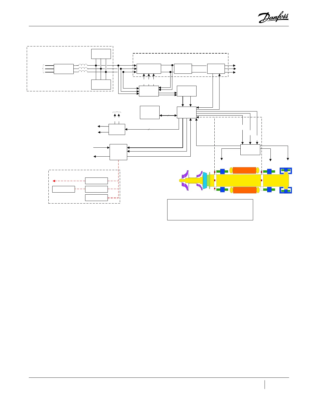
Figure 3-6 Compressor Control System Functional Block Diagram
3.4.1 Motor Drive System
Normally, AC power to the compressor remains on even when the compressor is in the idle state. The
compressor motor requires a variable-frequency three-phase source for variable-speed operation.
The AC line voltage is converted into a DC voltage by SCRs. DC capacitors at the SCR output serve
as energy storage and filter out the voltage ripple to provide a smooth DC voltage. The inverter that
converts the DC voltage into an adjustable three-phase AC voltage. Pulse Width Modulation (PWM)
signals from the BMCC control the inverter output frequency and voltage. By modulating the on and
off times of the inverter power switches, three-phase variable sinusoidal waveforms are obtained.
If the power should fail while the compressor is running, the motor switches into generator mode,
thereby sustaining the capacitor charge. The rotor can then spin down safely in a controlled sequence
preventing damage to components.
3.4.2 Soft-Start Board
The Soft-Start Board limits inrush current by progressively increasing the conduction angle of the
SCRs. This technique is used at compressor start-up while the DC capacitors are charging up.
The soft-start function and the variable-speed drive combined limit the inrush current at startup.
Backplane
2-3A
(Calibraon)
Front
Radial
Bearing
Rear
Radial
Bearing
Axial
Bearing
2-3A
(Calibraon)
2-3A
(Calibraon)
Customer
Chiller Control
Communicaons
Interface
Diagnosc
Terminal
Internet
RS-485 Comms
to Chiller or Building
Management System
User Interface
Serial
Driver
Module
+15VDC
+24VDC
To Motor Cooling Solenoids
To IGV Stepper Motor
Compressor
I/O
Board
0-10VDC
0-10VDC
Compressor
Inputs
Compressor
Outputs
Bearing PWM
Amplier
HV
+
not HV
-
+17VDC
not HV
-
+5VDC
Control
Feedback
+15VDC
+24VDC
+5VDC
+15VDC
Control
Feedback
Control
Feedback
So-Start
Controller
0-12 VDC
next (+) DC bus
Variable
Frequency
(0-750Hz)
AC Voltage
To Stator
V
a
V
b
V
c
DC/DC
Converter
460-853 VDC
15 VAC
+24VDC
HV
+
(+250VDC)
not HV
-
3-Phase
380-575VAC
50/60 Hz
+24VDC
Gang
Signals
Control
Feedback
Bearing
Motor
Compressor
Controller
(BMCC)
Control
+5VDC
+15VDC
-15VDC
+15VDC
External Expansion Valves
Sha Posion Outputs
Surge
Suppressor
Harmonic
Filter
Line
Reactor
EMI/EMC
Filter
External Power Components
3-Phase
380-575VAC
50/60 Hz
Half-Controlled
Recer
DC Link
Capacitors
1.35*V
in
0 VDC
3-Phase
Inverter
460-853 VDC
0 VDC
Motor Drive
Note:
All voltage levels shown have the following error tolerance:
DC (except the DC bus): ±5%
AC : ±10%
*
* 15 VAC is only applicable when DC-DC 100040
Not applicable for DCDC 100379 (Open Frame).

 Loading...


