30 of 114
M-AP-001-EN Rev. Q
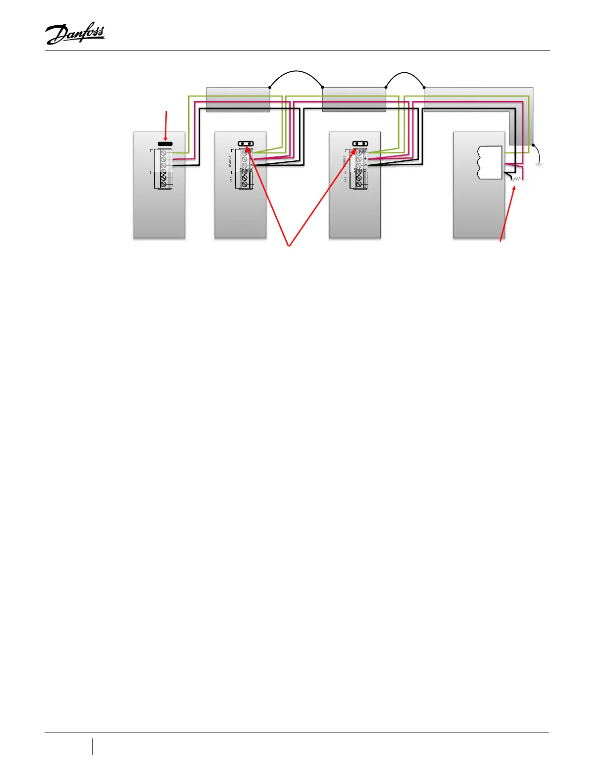
Figure 4-2 Modbus Grounding Diagram
RS485-1
I-Lock
CIM Board
RS485-1
I-Lock
CIM Board
RS485-1
I-Lock
CIM Board
REF
+
-
Shield
REF
+
-
Shield
REF
+
-
Shield
REF
-
+
120Ω
PLC
COM NETB NETA
MODBUS
Retain
Termination
Jumper in
Last Board
Remove Termination
Jumper in All
Intermediate Boards
Termination Resistor should only be included
if one is not included in the PLC. If the PLC
has a resistor installed, do not add an addi-
tional one. If the PLC does not have a resistor
installed, then one should be installed.

 Loading...


