28 of 114
M-AP-001-EN Rev. Q
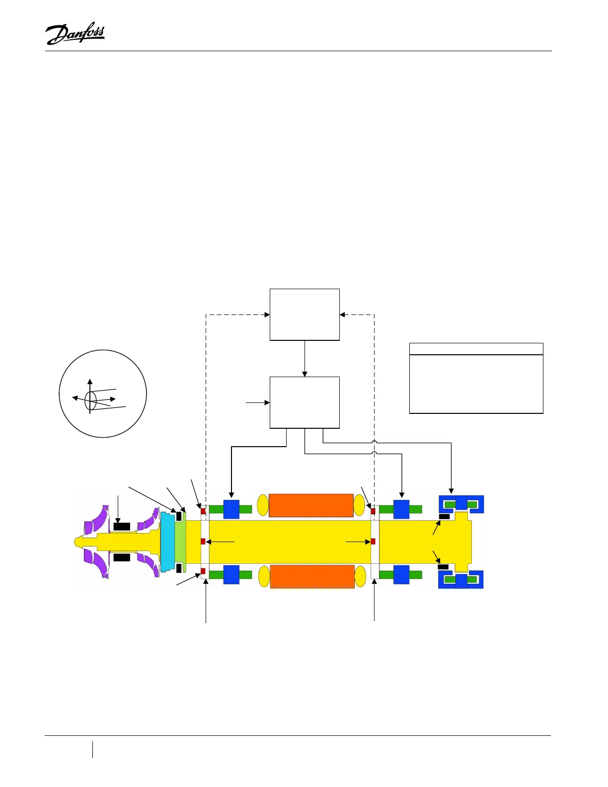
3.5.2 Bearing Control System
The Bearing Control System uses rotor position feedback to close the loop and maintain the rotor
in the correct running position (refer to "Figure 3-8 Magnetic Bearing Control System"). The Bearing
Controller issues position commands to the Bearing PWM Amplifier. The position commands consist
of five channels with each channel allocated to one of the five bearing actuator coils (one coil for each
axis). The amplifier uses Inverter technology to convert the low-voltage position commands to the
250VDC PWM signals that are applied to each bearing actuator coil.
Rotor position sensors are located on rings attached to the front and rear radial bearing assemblies.
The front sensor ring contains sensors that read the rotor position along the X, Y, and Z axes. The rotor
position along the Z (or axial) axis is read by measuring the distance between the sensor and a target
sleeve mounted on the rotor. The rear sensor ring contains sensors that read the position along the X
and Y axes. Information from the position sensors is continuously fed back to the bearing controller.
Figure 3-8 Magnetic Bearing Control System
Impellers
Z-axis
Position
S en so r
S en so r Ring
Front
Rad ial
Bearing
Motor
S en so r Ring
R ea r
Rad ial
Bearing
Axial
Bearing
X-axis
Position
S en so r
X-axis
Posi tion
S en so r
Touchdown
Bearings
Touchdown
Bearings
Target
Sleeve
Y-axis
Position
S en so r
Y-axis
Position
S en so r
Channels
Fx, Fy
Channels
Rx, Ry
Channel Axi
250 VDC
Position Command
Signals
Bearing-Mo tor-
Co mpressor
Controller (BMCC)
Bearing
PWM
Amplifier
Position FeedbackPosition Feedback
Axi s Bea ri ng Channel
X Front Radial Fx
Y Front Radial Fy
X Rear Radial Rx
Y Rear Radial Ry
Z Axi a l Axi
Shaft axes monitored
by position sensors
Y
X
Z
Shaft
Y
X
Z
Shaft

 Loading...


