4.7.8 Control Word According to Fieldbus
Profile
Illustration 4.31 Control Word According to Fiedbus Profile
To select Profidrive in the control word, set parameter 512
Telegram Profile to [0] Profidrive.
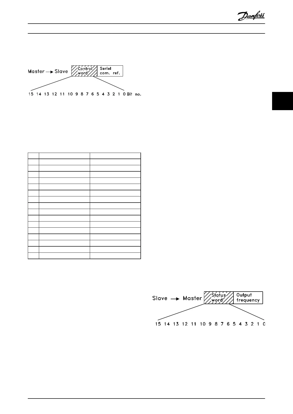
The control word is used to send commands from a master
(e.g. a PC) to a slave (frequency converter). MasterSlave.
Bit Bit = 0 Bit =1
00 OFF 1 ON 1
01 OFF 2 ON 2
02 OFF 3 ON 3
03 Coasting stop
04 Quick stop
05 Freeze outp. freq.
06 Ramp stop Start
07 Reset
08 Bus jog 1
09 Bus jog 2
10 Data not valid Data valid
11 Slow down
12 Catch-up
13 Select Setup (lsb)
14 Select Setup (msb)
15 Reversing
Table 4.15 Bit Definition
Bit 00-01-02, OFF1-2-3/ON1-2-3
Bit 00-01-02='0' causes ramp stop, which uses the ramp
time inparameters 207/208 or 209/210.
If Relay 123 is selected in parameter 323 Relay output, the
output relay is activated when the output frequency is 0
Hz.
Bit 00-01-02='1' means that the frequency converter can
start the motor if the other starting conditions are fulfilled.
Bit 03, Coasting stop
See description in chapter 4.7.6 Control Word According to
FC Protocol.
Bit 04, Quick stop
See description in chapter 4.7.6 Control Word According to
FC Protocol.
Bit 05, Freeze output frequency
See description in chapter 4.7.6 Control Word According to
FC Protocol.
Bit 06, Ramp stop/start
See description in chapter 4.7.6 Control Word According to
FC Protocol.
Bit 07, Reset
See description in chapter 4.7.6 Control Word According to
FC Protocol.
Bit 08, Jog 1
Bit 08="1" means that the output frequency is determined
by parameter 509 Bus jog 1.
Bit 09, Jog 2
Bit 09="1" means that the output frequency is determined
by parameter 510 Bus jog 2.
Bit 10, Data not valid/Data valid
See description in chapter 4.7.6 Control Word According to
FC Protocol.
Bit 11, Slow-down
Used to reduce the speed reference by the value in
parameter 219 Catch-up/slow-down reference.
Bit 11='0' does not cause any change to the reference.
Bit 11='1' means that the reference is reduced.
Bit 12, Catch-up
Used to increase the speed reference by the value in
parameter 219 Catch-up/slow-down reference.
Bit 12='0' does not cause any change to the reference.
Bit 12='1' means that the reference is increased.
If both Slow down and Catch-up are activated (Bits 11 and
12="1"), slow down has the highest priority, i.e. that the
speed reference is reduced.
Bit 13/14, Selection of Setup
See description in chapter 4.7.6 Control Word According to
FC Protocol.
Bit 15 Reversing
See description in chapter 4.7.6 Control Word According to
FC Protocol.
4.7.9
Status Word According to Profidrive
Protocol
Illustration 4.32 Status Word According to Profidrive Protocol
The status word is used to inform the master (e.g. a PC) of
the slave's (frequency converter) mode. SlaveMaster.
Programming
Design Guide
MG27E402 Danfoss A/S © Rev. May/2014 All rights reserved. 113
4 4

 Loading...


