1.11.2 Brake Set-up
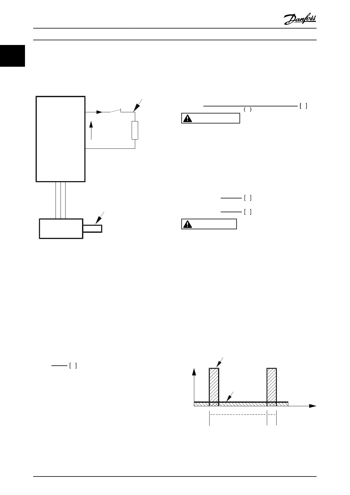
Illustration 1.9 shows a brake set-up with a frequency
converter.
P
peak,mec.
175ZA096.14
VLT
U
DC
I
termo
P
peak
P
avg
R
br
P
b, max
P
motor
η
INV
= 0.98
η
motor
= 0.9
Illustration 1.9 A Brake Set-up with a Frequency Converter
The expressions and acronyms that are used in
Illustration 1.9 are also used in the following sections.
1.11.3
Calculation of Brake Resistance
The following example and formula only apply to VLT 2800
Series.
To ensure that the frequency converter does not cut out
for safety reasons when the motor brakes, the resistance
value is selected on the basis of the peak braking effect
and the intermediate circuit voltage:
R
br
=
U
DC
²
P
PEAK
Ω
It can be seen that the brake resistance depends on the
intermediate circuit voltage (UDC).
With frequency converters that have a mains voltage of
3x380-480 V, the brake is active at 770 V (UDC); if the
frequency converter has a mains voltage of
3x200-240 V, the brake is active at 385 V (UDC).
Using the brake resistance (Rrec) recommended by Danfoss
guarantees that the frequency converter is able to brake at
the highest braking torque (M
BR
). The recommended brake
resistance is shown in chapter 1.11.13 Brake Resistors.
R
REC
calculated as:
R
REC
=
U
DC
²
× 100
P
motor
×
M
br
% × η
motor
× η
inv
Ω
WARNING
Ensure that the brake resistance can manage a voltage
of 850 V or 430 V, if Danfoss brake resistors are not
being used. Incompatible brake resistance could result in
equipment damage and/or personal injury.
ŋ
motor
is typically 0.90 and ŋ
INV
is typically 0.98. For 400 V
and 200 V frequency converters, R
REC
at 160% braking
torque can be written as:
400
V
R
REC
=
420139
P
motor
Ω
200
V
R
REC
=
105035
P
motor
Ω
CAUTION
The brake resistance selected should have an ohmic
value higher than 90% of the value recommended by
Danfoss. Selecting a lower brake resistance could result
in overcurrent, which can destroy the unit.
1.11.4 Calculation of Braking Power
When calculating the braking power, ensure that the mean
and peak powers can be dissipated to the brake resistor.
The mean power is determined by the period time of the
process, i.e. for how long the brake is applied in relation to
the period time of the process. The peak power is
determined by the braking torque, which means that
during braking the brake resistor must be able to dissipate
the energy input. Illustration 1.10 shows the relation
between mean power and peak power.
peak
P
avg
T
p
T
b
t [s]
175ZA094.13
Illustration 1.10 Mean Power and Peak Power
Introduction to VLT 2800 Design Guide
18 Danfoss A/S © Rev. May/2014 All rights reserved. MG27E402
1
1

 Loading...


