Preset ref.,
msb
Preset ref.,
lsb
Selection of
set-up
Output frequency
[Hz]
0 0 0 2.5
0 1 0 5
1 0 0 10
1 1 0 17.5
0 0 1 20
0 1 1 25
1 0 1 35
1 1 1 50
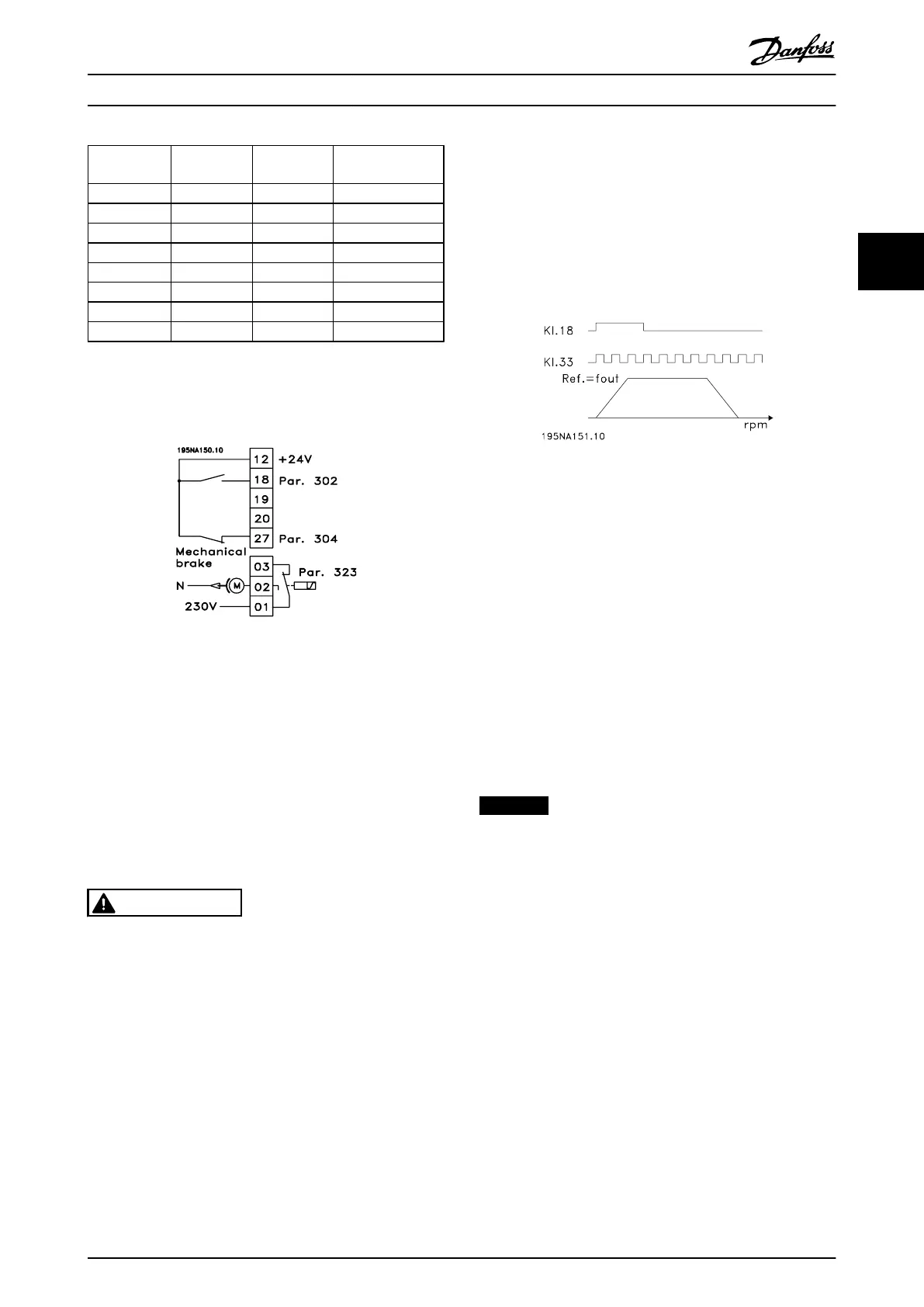
3.5.9 Connection of Mechanical Brake
Use of the relay for 230 V AC brake
Illustration 3.46 Connection of Mechanical Brake
•
Parameter 302 Digital input=[7] Start
•
Parameter 304 Digital input=[2] Coasting stop
inverted
•
Parameter 323 Relay output=[25] Mechanical brake
control
[25] Mechanical brake control='0' ⇒Brake is closed.
[25] Mechanical brake control='1' ⇒The brake is open.
See more detailed parameter settings in
chapter 3.4.13 Control of Mechanical Brake.
WARNING
Do not use the internal relay for DC brakes or brake
voltages > 250 V. There is a risk of equipment damage
and personal injury.
3.5.10 Counter Stop Through Terminal 33
The start signal (terminal 18) must be active, i.e. logical '1',
until the output frequency is equal to the reference. The
start signal (terminal 18 = logical '0') must then be
removed before the counter value in parameter 344
Counter value has managed to stop the frequency
converter.
Illustration 3.47 Counter Stop Through Terminal 33
•
Parameter 307 Digital input=[30] Pulse input
•
Parameter 343 Precise stop function=[1] Counter
stop with reset
•
Parameter 344 Counter value=100000
3.5.11
Use of Internal PID-Controller -
Closed Loop Process Control
1. Connect the frequency converter to mains and
motor cables as usual.
2. Connect transmitter (feedback signal) to +
terminal 12 and - terminal 60 (applies to 2-wire
transmitters 4-20 mA). (Connect transmitters with
0-10 V DC to + terminal 53 and - terminal 55).
NOTICE
Connect terminal 55 as - and terminal 60 as + for current
signal (0/4-20 mA) and terminal 53-55 for voltage signal
(0-10 V DC) if transmitters with separate voltage supply
are used.
3. Connect the start signal between terminal 12 and
18, 12-27 must be connected or set to no
function (Parameter 304 Digital input, term. 27=0).
4. Set all parameters in the Quick Menu and enter
the Main Menu (to enter the Main Menu: Press
[Quick Menu] and [+] simultaneously).
5. Set the following parameters:
•
Parameter 100 Configuration = [3] Process
controller closed loop
•
Parameter 101 Torque characteristic= [3] Variable
torque medium
•
If used with centrifugal pumps and fans.
•
Parameter 308 Terminal 53, analog input voltage=
[2] Feedback (for 0-10 V DC transmitters) or
Installation
Design Guide
MG27E402 Danfoss A/S © Rev. May/2014 All rights reserved. 59
3 3

 Loading...


