•
Parameter 314 Terminal 60, analogue input
current= [2] Feedback (for 4-20 mA transmitters)
•
Parameter 414 Minimum feedback FB
MIN=Minimum feedback scaling, must be set to
the minimum feedback value
•
Parameter 415 Maximum feedback,
FBMAX=Maximum feedback scaling, must be set
to the maximum feedback value
•
Example: Pressure transmitter 0-10 bar: Parameter
414 Minimum feedback FB MIN=0 and Parameter
415 Maximum feedback, FBMAX=10
•
Parameter 416 Process units=Process units: As
shown in the LCP (example: [4] bar)
•
Parameter 437 Process PID normal/inverse control=
[0] Normal: Reduce the output frequency when
the feedback signal increases
[1] Inverse: Increase the output frequency when
the feedback signal increases
•
Parameter 440 Proces PID proportioanl
gain=Proportional gain (P-gain) 0.3-1.0
(experienced value)
•
Parameter 441 Process PID integration
time=Integration time (I-time) 3-10 s (experienced
value)
•
Parameter 442 Process PID differentiation time
Differentiation time (D-time) 0-10 s (experienced
value)
•
Parameter 205 Maximum reference, RefMAX=Max.
reference is to be set equal to Parameter 415
Maximum feedback, FBMAX (example: 10 bar)
•
Parameter 215 Preset reference 1 (PRESET REF.
1)=Preset reference 1. Set the preset reference to
the wanted min. reference value (example: 5 bar)
•
(Parameter 205 Maximum reference, RefMAX and
Parameter 215 Preset reference 1 (PRESET REF. 1)
are shown in the process unit chosen in
parameter 416).
•
The value in brackets [ ] are data values
corresponding to the wanted function. Example:
Parameter 308 Terminal 53, analog input
voltageFeedback signal=[2] Feedback
•
If the motor is supposed to always run at a
minimum speed, a such can be selected in
Parameter 204 Minimum reference, Ref MIN=output
frequency low limit. (For pump works it is
typically 15-20 Hz).
•
With the above connections and settings, all
normal pump and fan applications work properly.
In certain cases it might be necessary to optimise
the PID-controllerr (Parameter 440 Proces PID
proportioanl gain, Parameter 441 Process PID
integration time and Parameter 442 Process PID
differentiation time
) beyond the mentioned
experienced values.
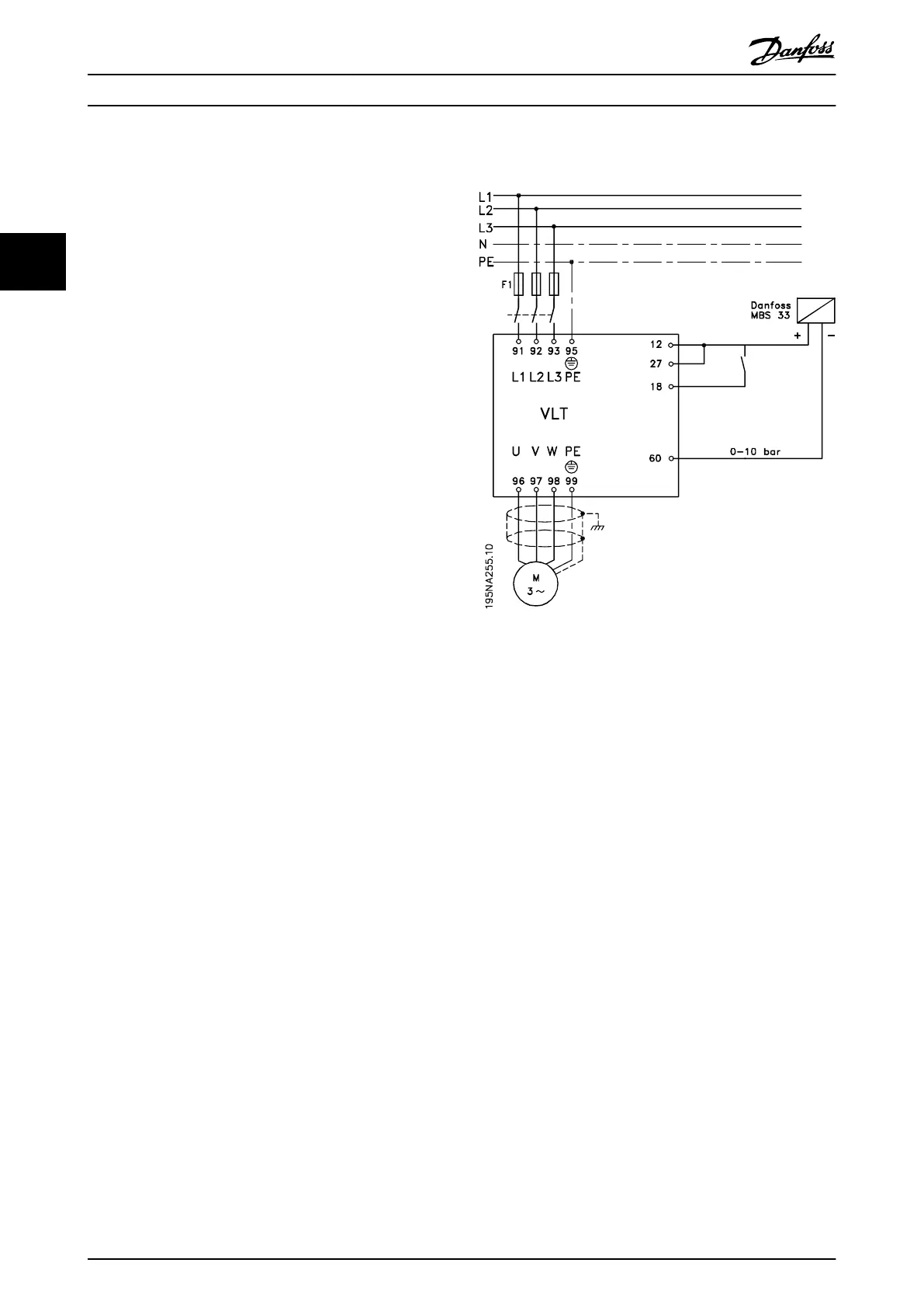
Illustration 3.48 Connection for Closed Loop Process Control
Installation Design Guide
60 Danfoss A/S © Rev. May/2014 All rights reserved. MG27E402
33

 Loading...


