1.11.10 Optimal Braking Using Resistor
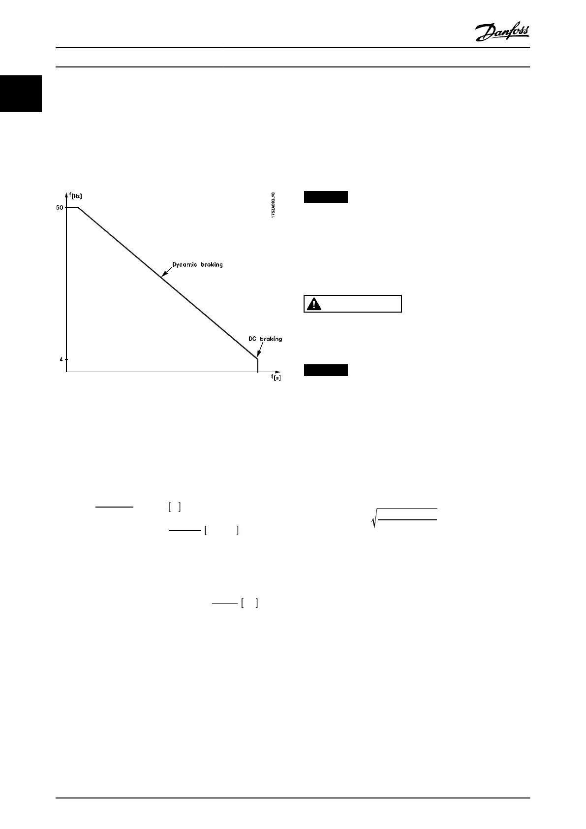
Dynamic braking is useful from maximum speed down to a
certain frequency. Below this frequency, DC braking is to
be applied as required. The most efficient way of doing
this is by using a combination of dynamic braking and DC
braking, as shown in Illustration 1.11.
Illustration 1.11 Combination of Dynamic Braking and DC
Braking
When changing from dynamic to DC braking, there is a
short period (2-6 ms) with very low braking torque.
How to calculate optimum DC-brake cut in frequency:
Slip
S
=
n
0
−
n
n
n
0
× 100 %
Synchronous
speed
n
0
=
f
× 60
p
1 /
min
f = frequency
p = no. of pole pairs
n
n
= speed of the rotor
DC
−
brake
cut
in
frequency
= 2 ×
s
×
f
100
Hz
1.11.11
Brake Cable
Max. length [m]: 20 m
Use a screened/armoured connection cable to the brake
resistor. Connect the screen to the conductive backplate at
the frequency converter and to the brake resistor metal
cabinet with cable clamps.
NOTICE
If Danfoss brake resistors are not used, there is a risk of
equipment damage. In this case, ensure the brake
resistor that is used in induction-free.
1.11.12 Protective Functions During
Installation
WARNING
Avoid overloads when a brake resistor is installed. The
heat generated from a brake resistor may result in a fire
risk.
NOTICE
The brake resistor should be fitted to a nonflammable
material to avoid the risk of fire.
For protection of the installation, fit a thermal relay that
cuts off the frequency converter if the brake current
becomes too high. Flat pack resistors are self-protecting.
Calculate the brake current setting of the thermal relay as
follows:
Itherm
relay
=
P
avg
R
brakeresistor
R
br
is the current brake resistor value calculated in
chapter 1.11.3 Calculation of Brake Resistance.
Illustration 1.12 shows an installation with a thermal relay.
The brake current setting of thermal relay for Danfoss 40%
brake resistors is shown in chapter 1.11.13 Brake Resistors.
Introduction to VLT 2800 Design Guide
20 Danfoss A/S © Rev. May/2014 All rights reserved. MG27E402
1
1

 Loading...


