EasyManuals Logo

Danfoss VLT 2800 Design Guide

Danfoss VLT 2800
162 pages
To Next Page IconTo Next Page
To Previous Page IconTo Previous Page
Page #23 background imageLoading...
Page #23 background image
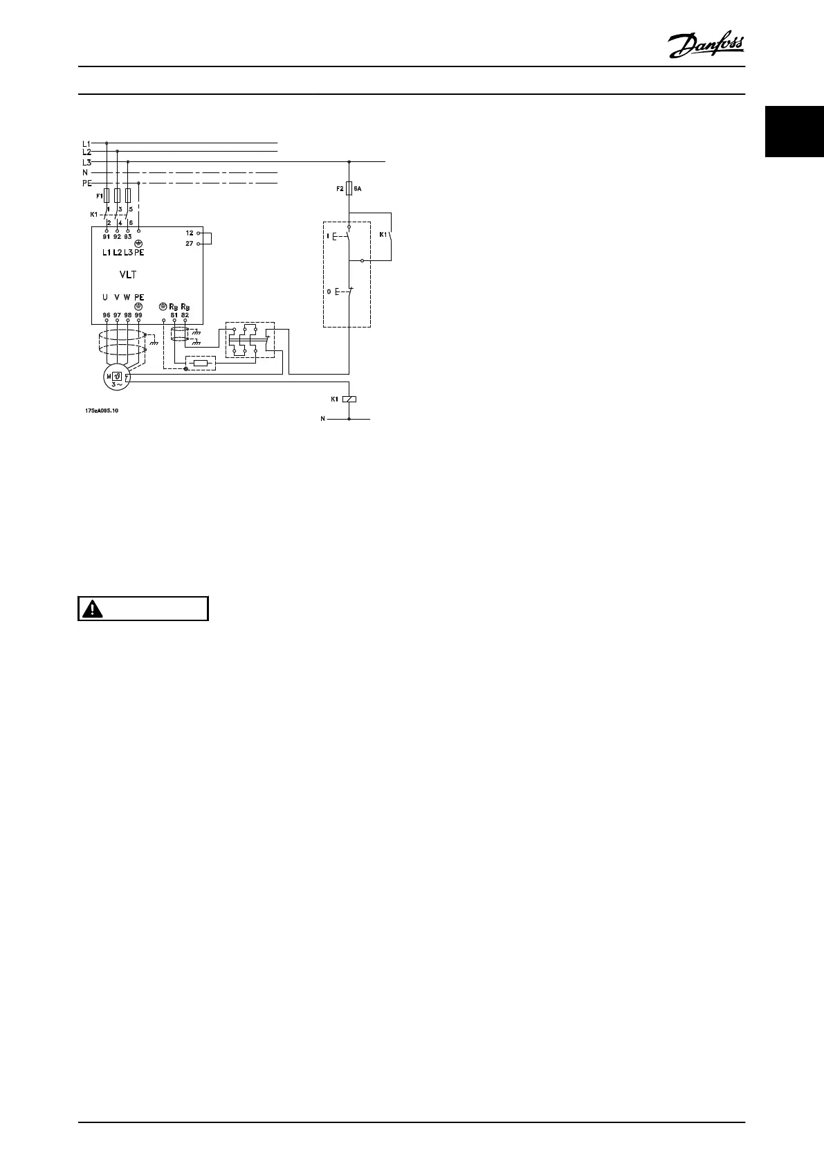
Illustration 1.12 Frequency Converter with Brake Resistor and
Thermal Switch
Some of the Danfoss brake resistors contain a thermal
switch (see chapter 1.11.13 Brake Resistors). This switch is
NC (normally closed) and can be used e.g. coasting stop
reverse between terminal 12 and 27. The frequency
converter coasts, if the thermal switch is opened.
CAUTION
The thermal switch is not a protective device. To protect
people and equipments from the risk of fire and
overheating, use a thermal switch as shown in
Illustration 1.12.
Introduction to VLT 2800 Design Guide
MG27E402 Danfoss A/S © Rev. May/2014 All rights reserved. 21
1
1

Table of Contents

Other manuals for Danfoss VLT 2800

Questions and Answers:

Question and Answer IconNeed help?

Do you have a question about the Danfoss VLT 2800 and is the answer not in the manual?

Danfoss VLT 2800 Specifications

General IconGeneral
Frequency50/60 Hz
EnclosureIP20
Input Voltage200-240V AC
Output Power Range0.37-2.2kW
Protection FeaturesOvercurrent, Overvoltage, Undervoltage, Overtemperature, Short Circuit
Communication InterfaceRS485
Operating Temperature-10°C to +40°C
Storage Temperature-25°C to +65 °C
Relative Humidity5 - 95% RH, non-condensing
Output Voltage0 - 100% of supply voltage

Related product manuals