4.8 Serial Communication Parameters
500 Address
Value:
Parameter 500 Protocol = FC protocol [0]
0 - 247 1
Parameter 500 Protocol = Metasys N2 [1]
1 - 255 1
Parameter 500 Protocol = MODBUS RTU [3]
1 - 247 1
Function:
This parameter allows the allocation of an address to each
frequency converter in a serial communication network.
Description of choice:
Allocate a unique address to the individual frequency
converter.
If the number of units connected (frequency converters +
master) is higher than 31, use a repeater.
Parameter 500 Address cannot be selected via the serial
communication, but must be preset via the control unit.
501
Baudrate
Value:
300 Baud (300 BAUD) [0]
600 Baud (600 BAUD) [1]
1200 Baud (1200 BAUD) [2]
2400 Baud (2400 BAUD) [3]
4800 Baud (4800 BAUD) [4]
9600 Baud (9600 BAUD) [5]
Function:
This parameter is for programming the speed at which
data is transmitted via the serial port. Baud rate is defined
as the number of bits transmitted per s.
Description of choice:
Set the frequency converter's transmission speed at a value
corresponding to the transmission speed of the master.
Parameter 501 Baudrate cannot be selected via the serial
port, but must be preset via the operating unit.
502
Coasting Stop
Value:
Digital input (DIGITAL INPUT) [0]
Serial port (SERIAL PORT) [1]
Logic and (LOGIC AND) [2]
Logic or (LOGIC OR) [3]
Function:
Parameters 502-508 allow a selection between controlling
the adjustable frequency drive via the digital inputs and/or
via the serial port.
If [1] Serial port is selected, the relevant command can only
be activated if a command is given via the serial port.
In the case of [2] Logic and the function must also be
activated via a digital input.
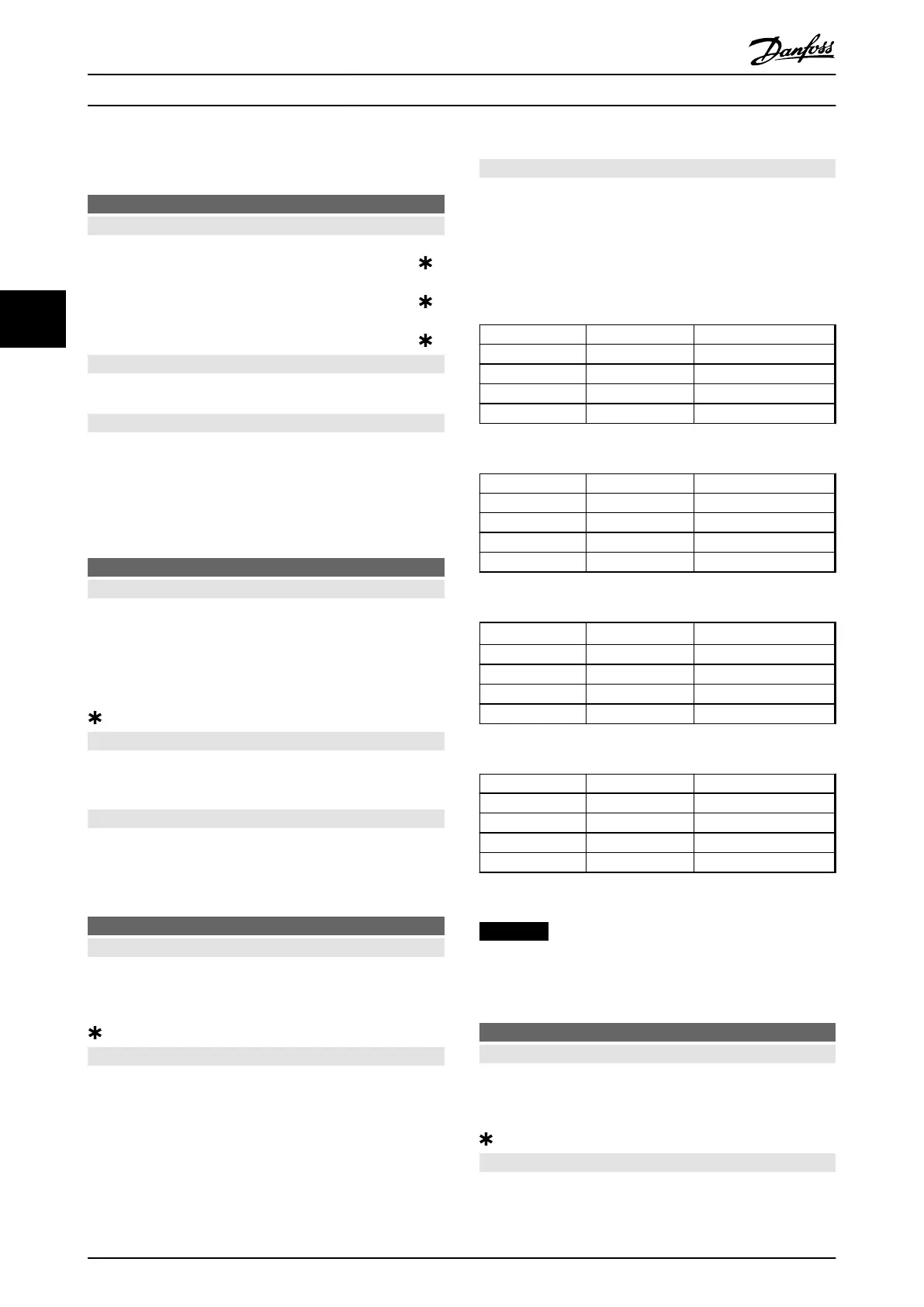
Description of choice:
Table 4.18, Table 4.19, Table 4.20, and Table 4.21 show when
the motor is running and when it is coasting, when each
of the following is selected:
•
[0] Digital input
•
[1] Serial port
•
[2] Logic and or [3] Logic or
Dig. input Ser. port Function
0 0 Coasting
0 1 Coasting
1 0 Motor running
1 1 Motor running
Table 4.18 Function Description for [0] Digital input
Dig. input Ser. port Function
0 0 Coasting
0 1 Motor running
1 0 Coasting
1 1 Motor running
Table 4.19 Function Description for [1] Serial port
Dig. input Ser. port Function
0 0 Coasting
0 1 Motor running
1 0 Motor running
1 1 Motor running
Table 4.20 Function Description for [2] Logic and
Dig. input Ser. port Function
0 0 Coasting
0 1 Coasting
1 0 Coasting
1 1 Motor running
Table 4.21 Function Description for [3] Logic or
NOTICE
Coasting stop and bit 03 in the control word are active at
logic '0'.
503 Quick-stop
Value:
Digital input (DIGITAL INPUT) [0]
Serial port (SERIAL PORT) [1]
Logic and (LOGIC AND) [2]
Logic or (LOGIC OR) [3]
Function:
See function description for parameter 502 Coasting stop.
Programming
Design Guide
116 Danfoss A/S © Rev. May/2014 All rights reserved. MG27E402
44

 Loading...


