Description of choice:
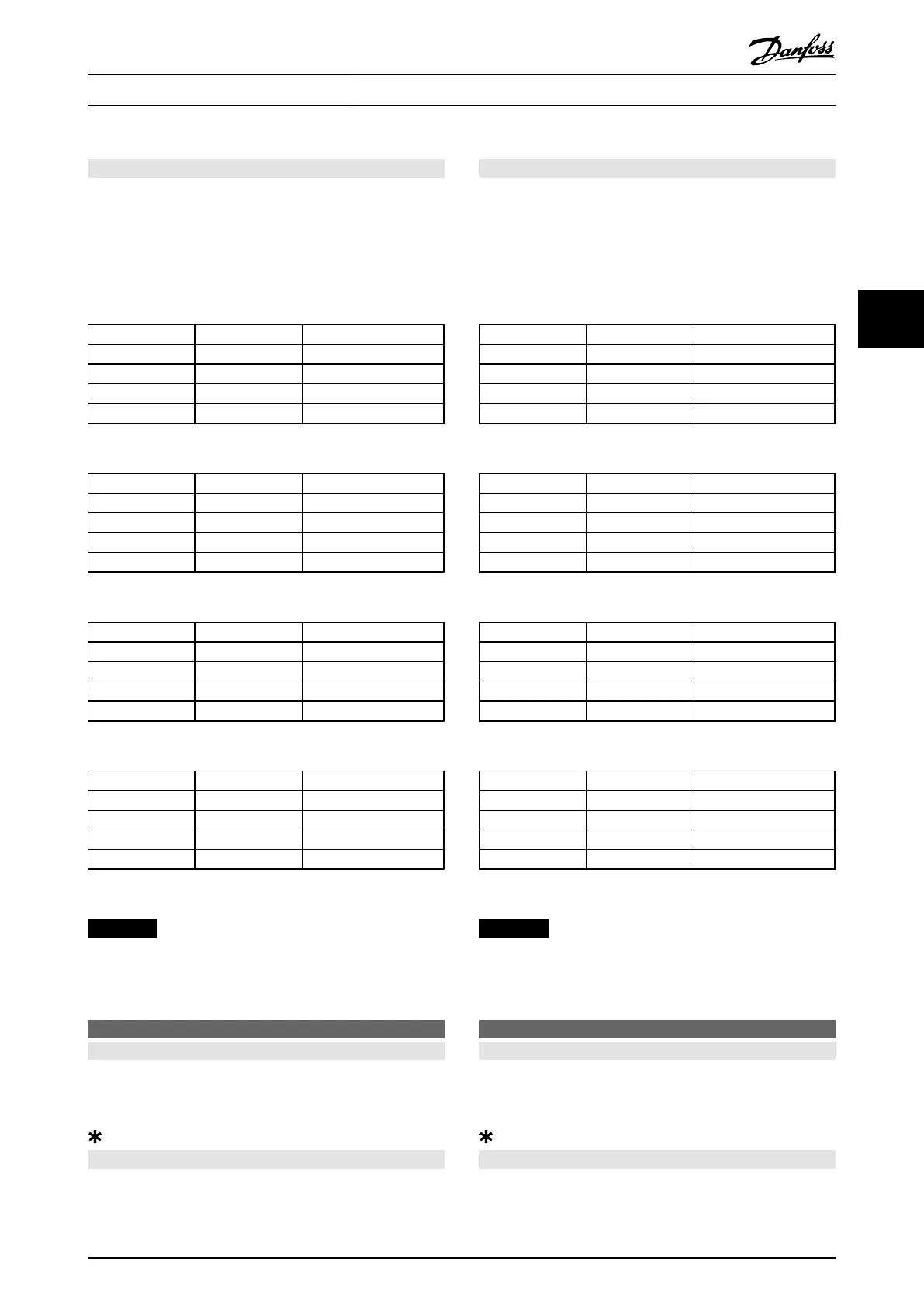
Table 4.22, Table 4.23, Table 4.24, and Table 4.25 show when
the motor is running and when it is in Quick-stop mode,
when each of the following is selected:
•
[0] Digital input
•
[1] Serial port
•
[2] Logic and or [3] Logic or
Dig. input Serial port Function
0 0 Quick-stop
0 1 Quick-stop
1 0 Motor running
1 1 Motor running
Table 4.22 Function Description for [0] Digital input
Dig. input Serial port Function
0 0 Quick-stop
0 1 Motor running
1 0 Quick-stop
1 1 Motor running
Table 4.23 Function Description for [1] Serial port
Dig. input Serial port Function
0 0 Quick-stop
0 1 Motor running
1 0 Motor running
1 1 Motor running
Table 4.24 Function Description for [2] Logic and
Dig. input Serial port Function
0 0 Quick-stop
0 1 Quick-stop
1 0 Quick-stop
1 1 Motor running
Table 4.25 Function Description for [3] Logic or
NOTICE
Quick-stop inverse and bit 04 in the control word are
active at logic '0'.
504 DC brake
Value:
Digital input (DIGITAL INPUT) [0]
Serial port (SERIAL PORT) [1]
Logic and (LOGIC AND) [2]
Logic or (LOGIC OR) [3]
Function:
See function description for parameter 502 Coasting stop.
Description of choice:
Table 4.26, Table 4.27, Table 4.28, and Table 4.29 show when
the motor is running and the DC braking when each of the
following is selected:
•
[0] Digital input
•
[1] Serial port
•
[2] Logic and or [3] Logic or
Dig. input Ser. port Function
0 0 DC braking
0 1 DC braking
1 0 Motor running
1 1 Motor running
Table 4.26 Function Description for [0] Digital input
Dig. input Ser. port Function
0 0 DC braking
0 1 Motor running
1 0 DC braking
1 1 Motor running
Table 4.27 Function Description for [1] Serial port
Dig. input Ser. port Function
0 0 DC braking
0 1 Motor running
1 0 Motor running
1 1 Motor running
Table 4.28 Function Description for [2] Logic and
Dig. input Ser. port Function
0 0 DC braking
0 1 DC braking
1 0 DC braking
1 1 Motor running
Table 4.29 Function Description for [3] Logic or
NOTICE
DC braking inverse and bit 02 in the control word are
active at logic '0'.
505 Start
Value:
Digital input (DIGITAL INPUT) [0]
Serial port (SERIAL PORT) [1]
Logic and (LOGIC AND) [2]
Logic or (LOGIC OR) [3]
Function:
See function description for parameter 502 Coasting stop.
Programming
Design Guide
MG27E402 Danfoss A/S © Rev. May/2014 All rights reserved. 117
4 4

 Loading...


