Description of choice:
Table 4.30, Table 4.31, Table 4.32, and Table 4.33 show when
the motor has stopped and when the frequency converter
has a start command when each of the following is
selected:
•
[0] Digital input,
•
[1] Serial port,
•
[2] Logic and or [3] Logic or.
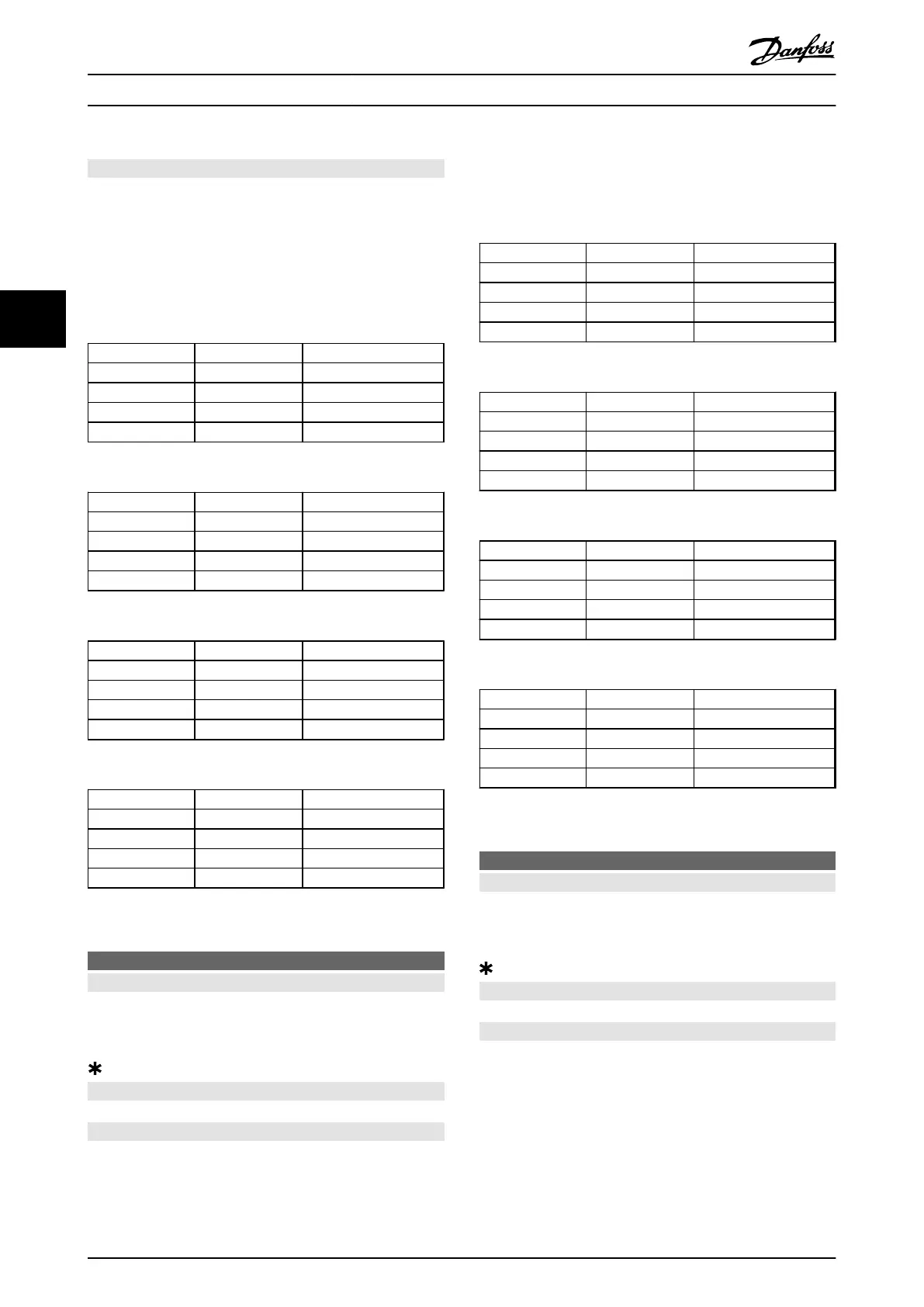
Dig. input Ser. port Function
0 0 Stop
0 1 Stop
1 0 Start
1 1 Start
Table 4.30 Function Description for [0] Digital input
Dig. input Ser. port Function
0 0 Stop
0 1 Start
1 0 Stop
1 1 Start
Table 4.31 Function Description for [1] Serial port
Dig. input Ser. port Function
0 0 Stop
0 1 Stop
1 0 Stop
1 1 Start
Table 4.32 Function Description for [2] Logic and
Dig. input Ser. port Function
0 0 Stop
0 1 Start
1 0 Start
1 1 Start
Table 4.33 Function Description for [3] Logic or
506
Reversing
Value:
Digital input (DIGITAL INPUT) [0]
Serial port (SERIAL PORT) [1]
Logic and (LOGIC AND) [2]
Logic or (LOGIC OR) [3]
Function:
See function description for parameter 502 Coasting stop.
Description of choice:
Table 4.34, Table 4.35, Table 4.36, and Table 4.37 show when
the motor is running clockwise and anti-clockwise when
each of the following is selected:
•
[0] Digital input,
•
[1] Serial port,
•
[2] Logic and or [3] Logic or.
Dig. input Ser. port Function
0 0 Clockwise
0 1 Clockwise
1 0 Anti-clockwise
1 1 Anti-clockwise
Table 4.34 Function Description for [0] Digital input
Dig. input Ser. port Function
0 0 Clockwise
0 1 Anti-clockwise
1 0 Clockwise
1 1 Anti-clockwise
Table 4.35 Function Description for [1] Serial port
Dig. input Ser. port Function
0 0 Clockwise
0 1 Clockwise
1 0 Clockwise
1 1 Anti-clockwise
Table 4.36 Function Description for [2] Logic and
Dig. input Ser. port Function
0 0 Clockwise
0 1 Anti-clockwise
1 0 Anti-clockwise
1 1 Anti-clockwise
Table 4.37 Function Description for [3] Logic or
507
Selection of Setup
Value:
Digital input (DIGITAL INPUT) [0]
Serial communication (SERIAL PORT) [1]
Logic and (LOGIC AND) [2]
Logic or (LOGIC OR) [3]
Function:
See function description of parameter 502 Coasting stop.
Description of choice:
Table 4.38, Table 4.39, Table 4.40, and Table 4.41 show
which Set-up (parameter 004 Active Setup) is selected for
each of the following:
•
[0] Digital input,
•
[1] Serial communication,
•
[2] Logic and or [3] Logic or.
Programming
Design Guide
118 Danfoss A/S © Rev. May/2014 All rights reserved. MG27E402
44

 Loading...


