3.4.12 Tightening Torque for Power
Terminals
Tighten power and ground terminals with the following
torques:
VLT Terminals Torque [Nm]
2803-2875 Power mains brake 0.5-0.6
Ground 2-3
2880-2882,
2840 PD2
Power mains brake 1.2-1.5
Ground 2-3
3.4.13 Control of Mechanical Brake
In lifting/lowering applications, it’s necessary to control an
electromagnetic brake. The brake is controlled using a
relay output or digital output (terminal 46). The output
must be kept closed (voltage-free) for the period of time
during which the frequency converter is not able to
support the motor, for example due to the load being too
high. Select [25] Mechanical brake control in parameter 323
Relay output 1-3 or parameter 341 Digitial/Pulse output
terminal 46 for applications with an electromagnetic brake.
When the output frequency exceeds the brake cut-out
value set in parameter 138 Brake cut out value, the brake is
released if the motor current exceeds the preset value in
parameter 140 Current, minimum value. The brake is
engaged when the output frequency is less than the brake
engaging frequency, which is set in parameter 139 Brake
cut in frequency.
If the frequency converter is in alarm status or in an
overvoltage situation, the mechanical brake is cut in
immediately.
NOTICE
This application is only for lifting/lowering without a
counterbalance.
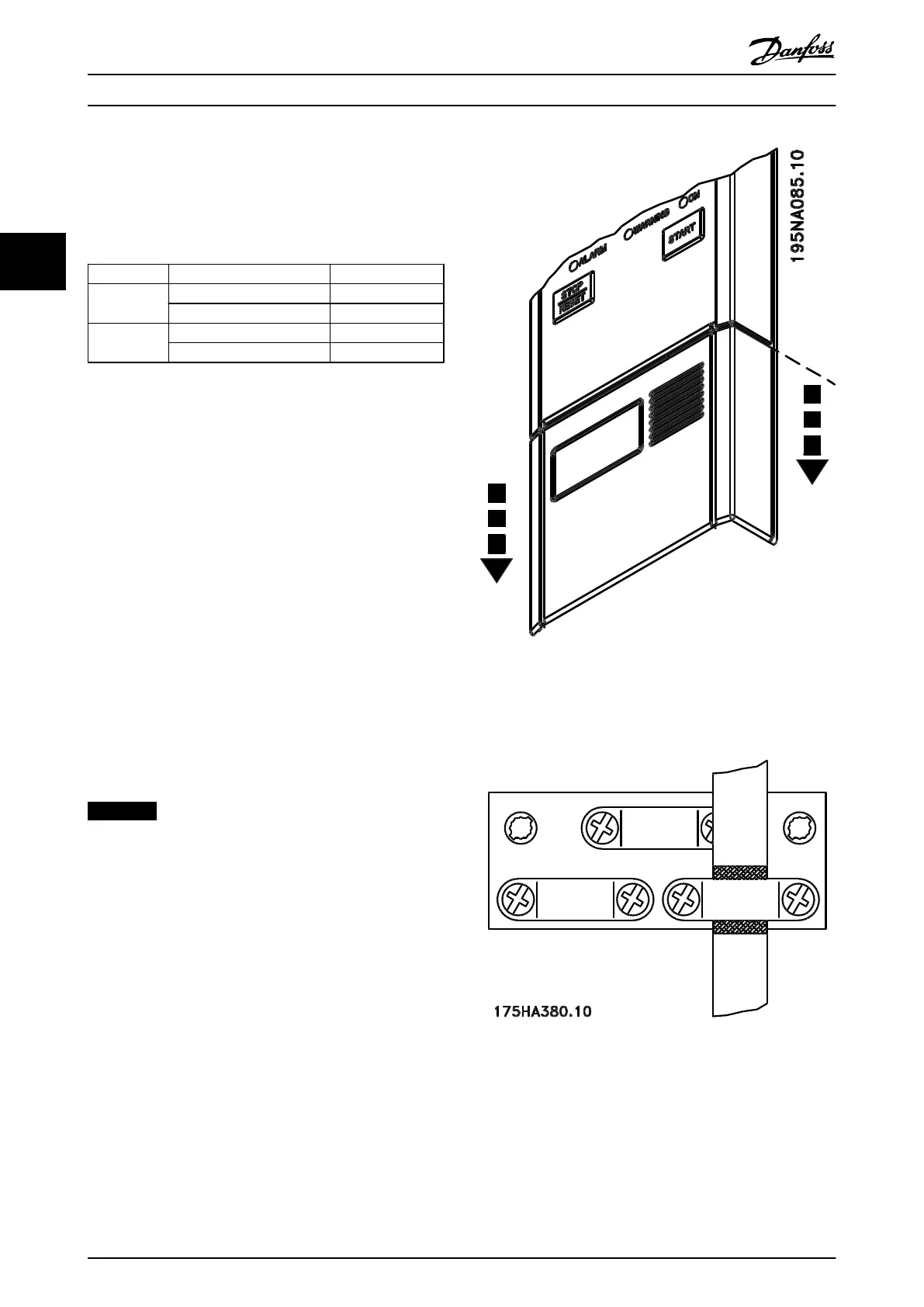
3.4.14 Access to Control Terminals
All terminals to the control cables are located underneath
the protective plate on the front of the frequency
converter. Remove the protective plate by pulling it
downwards, as shown in Illustration 3.31.
Illustration 3.31 Remove the Protective Cover
3.4.15
Control Cables
Illustration 3.32 Screen Control Cables
Use acreened/armoured control cables. Connect the screen
to the frequency converter chassis with a clamp. Normally,
the screen must also be connected to the chassis of the
controlling unit (use the instructions for the unit in
question). In connection with very long control cables and
analog signals, 50/60 Hz ground loops may occur because
Installation
Design Guide
52 Danfoss A/S © Rev. May/2014 All rights reserved. MG27E402
33

 Loading...


