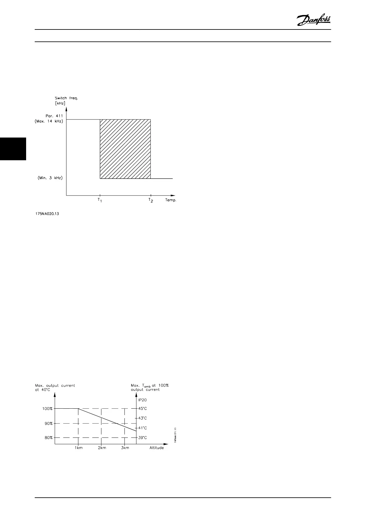
The function ensures that the frequency converter
automatically adjusts the switching frequency between f
sw,
min
and f
sw, max
(parameter 411 Switching frequency), as
shown in Illustration 5.2.
Illustration 5.2 Switching Frequencies vs. Temperature
When an LC filter is used, the minimum switching
frequency is 4.5 kHz.
5.1.10
Derating for Air Pressure
Protective Extra Low Voltage (PELV) requirements stated in
IEC 61800-5-1 are not fulfilled at altitudes above 2000 m
(6562 ft.). Contact Danfoss for further information.
Below 1000 m derating is not necessary.
Above 1000 m, derate the ambient temperature (T
AMB
) or
maximum output current (I
MAX
) in accordance with the
diagram in Illustration 5.3:
1. Derating of output current versus altitude at
T
AMB
=maximum 45 °C.
2. Derating of max. T
AMB
versus altitude at 100%
output current.
Illustration 5.3 Derating for Air Pressure
5.1.11 Derating for Running at Low Speed
When a motor is connected to a frequency converter, it is
necessary to ensure adequate cooling of the motor. At low
RPM values, the motor fan is not able to supply an
adequate volume of cooling air. This problem occurs when
the load torque is constant (for example, with a conveyor
belt) across the full regulating range. The reduced amount
of ventilation determines the permissible torque in
continuous operation. If the motor is to run continuously
at an RPM lower than half the rated value, extra cooling air
must be supplied to the motor. Instead of providing extra
cooling, reduce the motor load ratio by selecting a larger
motor. However, the design of the frequency converter
puts limits on the size of motors that can be connected to
the frequency converter.
5.1.12
Derating for Long Motor Cables
The frequency converter has been tested using a 75 m
unscreened/unarmoured cable and a 25 m screened/
armoured cable and has been designed to work using a
motor cable with a rated cross-section. If a cable with a
larger cross-section is required, reduce the output current
by 5% for each step the cable cross-section is increased.
(Increased cable cross-section leads to increased
capacitance to ground, and thus to an increased ground
leakage current).
5.1.13
Derating for High Switching
Frequency
A higher switching frequency (to be set in parameter 411
Switching frequency) leads to higher losses in the
electronics of the frequency converter.
VLT 2800 has a pulse pattern in which it is possible to set
the switching frequency from 3.0- 10.0/14.0 kHz.
The frequency converter automatically derates the rated
output current I
VLT,N,
when the switching frequency
exceeds 4.5 kHz.
In both cases, the reduction is carried out linearly, down to
60% of I
VLT,N
.
All about VLT 2800
Design Guide
130 Danfoss A/S © Rev. May/2014 All rights reserved. MG27E402
55

 Loading...


