3.4.16 Control Terminals
See chapter 3.3.9 Grounding of Screened/armoured Control Cables for the correct termination of control cables.
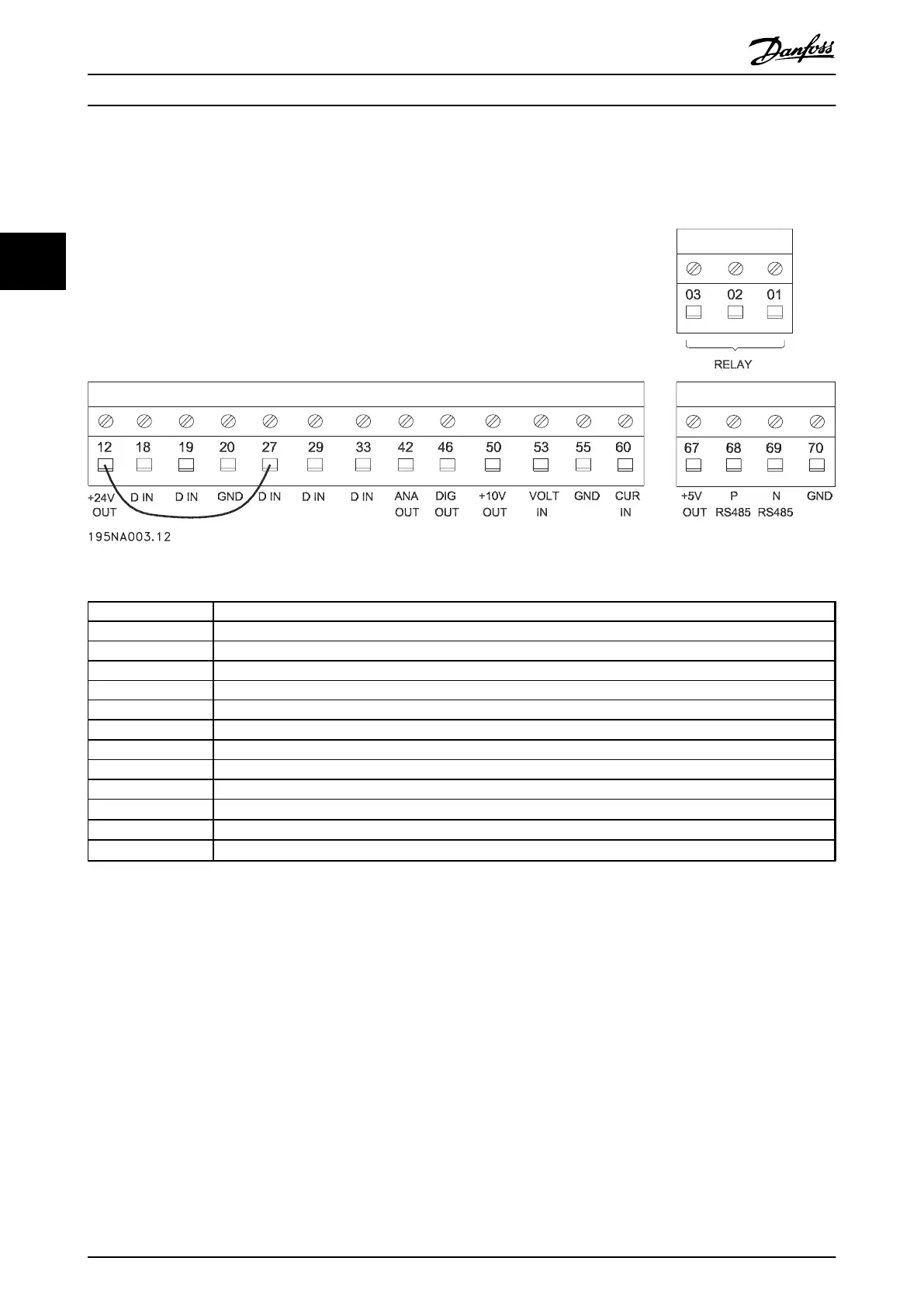
Illustration 3.34 Control Terminals
No. Function
01-03 Relay outputs 01-03 can be used for indicating status and alarms/warnings.
12 24 V DC voltage supply.
18-33 Digital inputs.
20, 55 Common frame for input and output terminals.
42 Analog output for displaying frequency, reference, current or torque.
46
1
Digital output for displaying status, warnings or alarms, as well as frequency output.
50 +10 V DC supply voltage for potentiometer or thermistor.
53 Analog voltage input 0-10 V DC.
60 Analog current input 0/4-20 mA.
67
1)
+ 5 V DC supply voltage to Profibus.
68, 69
1)
RS-485, serial communication.
70
1)
Frame for terminals 67, 68 and 69. Normally this terminal is not to be used.
Table 3.8 Functions of Control Terminals
1) The terminals are not valid for DeviceNet/CANopen. See DeviceNet Manual for further details.
Installation Design Guide
54 Danfoss A/S © Rev. May/2014 All rights reserved. MG27E402
33

 Loading...


