209 Ramp-up time 2
Value:
0.02-3600.00 s
3.00 s (VLT 2803-2875)
10.00 s (VLT 2880-2882)
Function:
See description of parameter 207 Ramp-up time 1.
Description of choice:
Set the required ramp-up time. Shift from ramp 1 to ramp
2 by activating Ramp 2 via a digital input.
210 Ramp-down time 2
Value:
0.02-3600.00 s
3.00 s (VLT 2803-2875)
10.00 s (VLT 2880-2882)
Function:
See description of
parameter 208 Ramp-down time 1.
Description of choice:
Set the required ramp-down time. Shift from ramp 1 to
ramp 2 by activating Ramp 2 via a digital input.
211
Job ramp time
Value:
0.02-3600.00 s
3.00 s (VLT 2803-2875)
10.00 s (VLT 2880-2882)
Function:
The jog ramp time is the acceleration/deceleration time
from 0 Hz to the rated motor frequency f
M,N
(parameter
104 Motor frequency, f
M,N
). It is assumed that the output
current does not reach the current limit (set in parameter
221 Current limit I
LIM
).
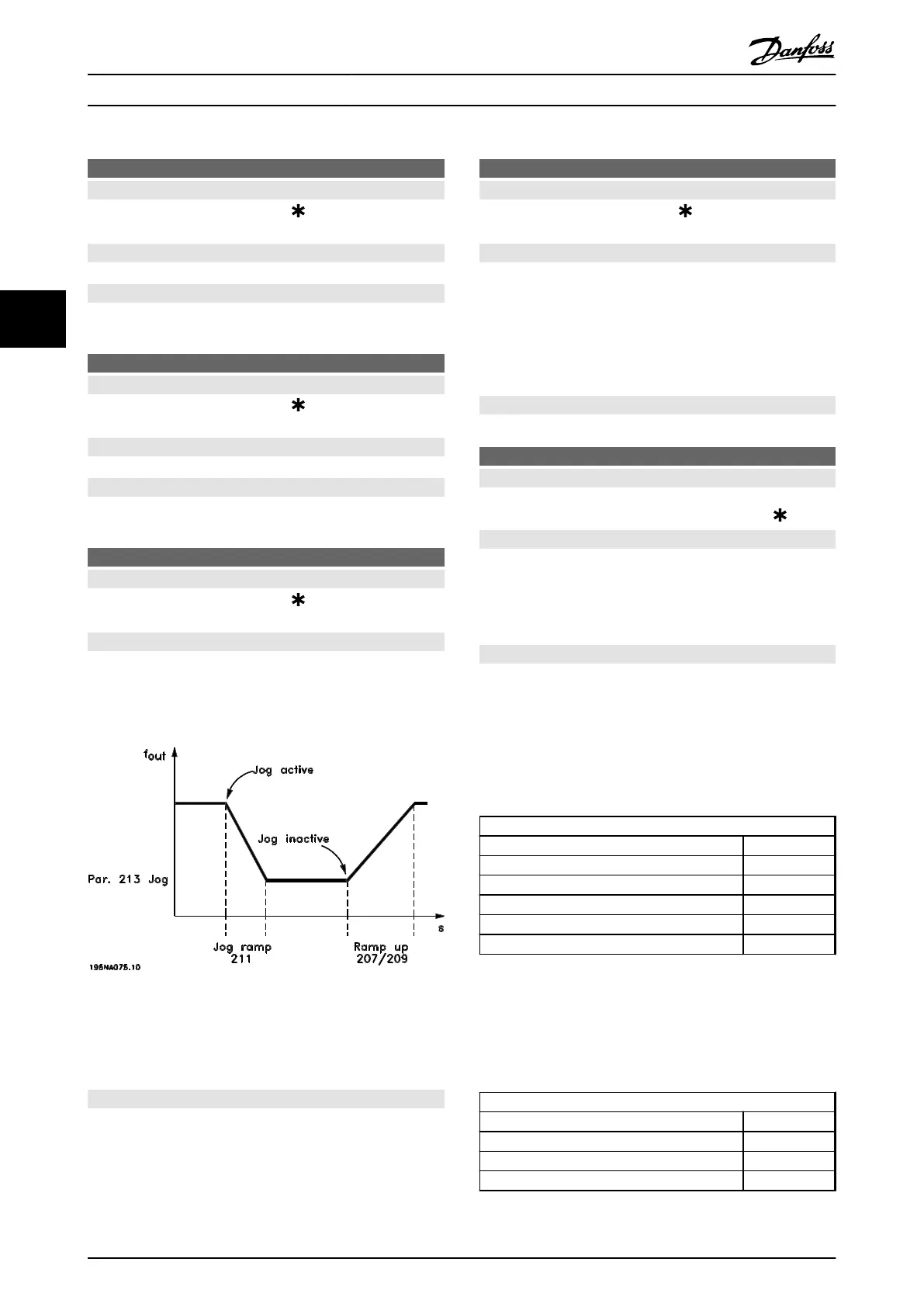
Illustration 4.10 Jog Ramp
The jog ramp time starts if a jog-signal is given via the
LCP, one of the digital inputs or the serial communication
port.
Description of choice:
Set the required ramp time.
212
Quick-stop ramp-down time
Value:
0.02-3600.00 s
3.00 s (VLT 2803-2875)
10.00 s (VLT 2880-2882)
Function:
The quick-stop ramp-down time is the deceleration time
from the rated motor frequency to 0 Hz, provided no
overvoltage arises in the inverter because of generating
operation of the motor, or if the generated current
exceeds the current limit in parameter 221 Current limit I
LIM
.
Quick-stop is activated via one of the digital inputs or the
serial communication.
Description of choice:
Set the required ramp-down time.
213
Jog frequency
Value:
0.0 - Parameter 202 Output frequency high
limit, f
MAX
10.0 Hz
Function:
Jog frequency f
JOG
means a fixed output frequency that
the frequency converter supplies to the motor when the
jog function is activated. Jog can be activated via the
digital inputs, serial communication or via the LCP, on the
condition that this is active in parameter 015 Local jog.
Description of choice:
Set the required frequency.
The example shows how the resulting reference is
calculated when Preset references is used with Sum and
Relative in parameter 214 Reference function. The formula
for the calculation of the resulting reference is described in
chapter 5 All about VLT 2800. Also see Illustration 4.7 for
more details.
The following parameters are preset:
Parameter 204 Minimum reference
10 Hz
Parameter205 Maximum reference
50 Hz
Parameter215 Preset reference
15 %
Parameter308 Term. 53, Analogue input
Reference
Parameter309 Term. 53, min. scaling
0 V
Parameter310 Term. 53, max. scaling
10 V
When parameter 214 Reference function is set to [0] Sum,
one of the preset Preset references (parameter 215-218) is
added to the external references as a percentage of the
reference range. If terminal 53 is applied to an analog
input voltage of 4 V, the resulting reference is:
Parameter 214 Reference function
= Sum [0]:
Parameter 204 Minimum reference
10.0 Hz
Reference contribution at 4 V 16.0 Hz
Parameter 215 Preset reference
6.0 Hz
Resulting reference 32.0 Hz
Programming Design Guide
80 Danfoss A/S © Rev. May/2014 All rights reserved. MG27E402
44

 Loading...


