8.10 Wiring Conguration for a
Submersible Pump
The system consists of a submersible pump controlled by a
Danfoss VLT
®
AQUA Drive and a pressure transmitter. The
transmitter gives a 4–20 mA feedback signal to the drive,
which keeps a constant pressure by controlling the speed
of the pump. To design a drive for a submersible pump
application, there are a few important issues to consider.
Select the drive according to motor current.
•
The CAN motor is a motor with a stainless steel
can between the rotor and stator that contains a
larger and a more magnetic resistant air-gap than
on a normal motor. This weaker eld results in
the motors being designed with a higher rated
current than a normal motor with similar rated
power.
•
The pump contains thrust bearings that are
damaged when running below minimum speed,
which is normally 30 Hz.
•
The motor reactance is nonlinear in submersible
pump motors and, therefore, automatic motor
adaption (AMA) may not be possible. Normally,
submersible pumps are operated with long motor
cables that might eliminate the nonlinear motor
reactance and enable the drive to perform AMA.
If AMA fails, the motor data can be set from
parameter group 1-3* Adv. Motor Data (see the
motor datasheet). If AMA has succeeded, the
drive compensates for the voltage drop in the
long motor cables. If the advanced motor data
are set manually, the length of the motor cable
must be considered to optimize system
performance.
•
It is important that the system is operated with a
minimum of wear and tear on the pump and
motor. A Danfoss sine-wave
lter can lower the
motor insulation stress and increase lifetime
(check actual motor insulation and the drive
dU/dt specication). Most manufacturers of
submersible pumps require the use of output
lters.
•
EMC performance can be dicult to achieve
because the special pump cable, which is able to
withstand the wet conditions in the well, is
normally unshielded. A solution could be to use a
shielded cable above the well and attach the
shield to the well pipe, if it is made of steel. A
sine-wave lter also reduces the EMI from
unshielded motor cables.
The special CAN motor is used because of the wet instal-
lation conditions. Design the system according to output
current to be able to run the motor at nominal power.
To prevent damage to the thrust bearings of the pump,
and to ensure sucient motor cooling as quickly as
possible, it is important to ramp the pump from stop to
minimum speed as quick as possible. Most submersible
pump manufacturers recommend that the pump ramps to
minimum speed (30 Hz) in maximum 2–3 s. The VLT
®
AQUA Drive FC 202 is designed with initial and nal ramp
for these applications. The initial and nal ramps are 2
individual ramps, where initial ramp, if enabled, ramps the
motor from stop to minimum speed and automatically
switches to normal ramp, when minimum speed is
reached. Final ramp does the opposite from minimum
speed to stop in a stop situation. Consider also enabling
advanced minimum speed monitoring as described in the
design guide.
To achieve extra pump protection, use the dry-run
detection function. For more information, see the
programming guide.
Pipe-ll mode can be enabled to prevent water
hammering. The Danfoss drive can
ll the vertical pipes
using the PID controller to ramp up the pressure slowly
with a user-specied rate (units/second). If enabled, the
drive enters pipe-ll mode when it reaches minimum
speed after start-up. The pressure is slowly ramped up until
it reaches a user-specied lled setpoint, where the drive
automatically disables pipe ll mode and continues in
normal closed-loop operation.
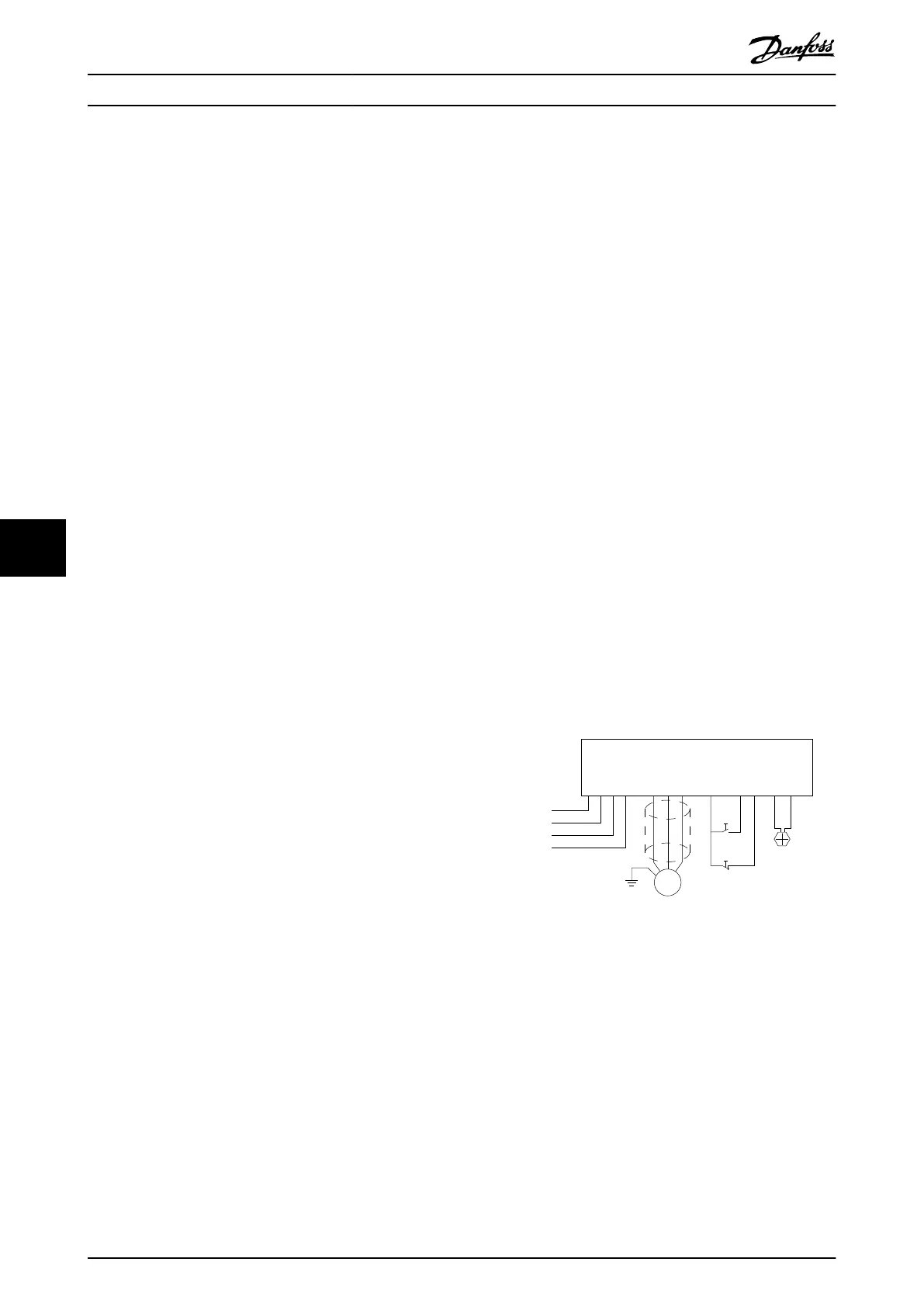
Electrical Wiring
130BA727.10
M
PE
L1 L3 U V W 12 18 27 13 54
L2 PE
Mains
2 wire 4-20mA
Pressure
Transmitter
Start
Stop
Illustration 8.4 Wiring for Submersible Pump Application
Wiring Conguration Exampl... VLT® AQUA Drive FC 202
78 Danfoss A/S © 09/2018 All rights reserved. MG21A502
88

 Loading...


