EasyManua.ls Logo

Danfoss VLT AQUA Drive FC 202

Danfoss VLT AQUA Drive FC 202
162 pages
To Next Page IconTo Next Page
To Previous Page IconTo Previous Page
Loading...
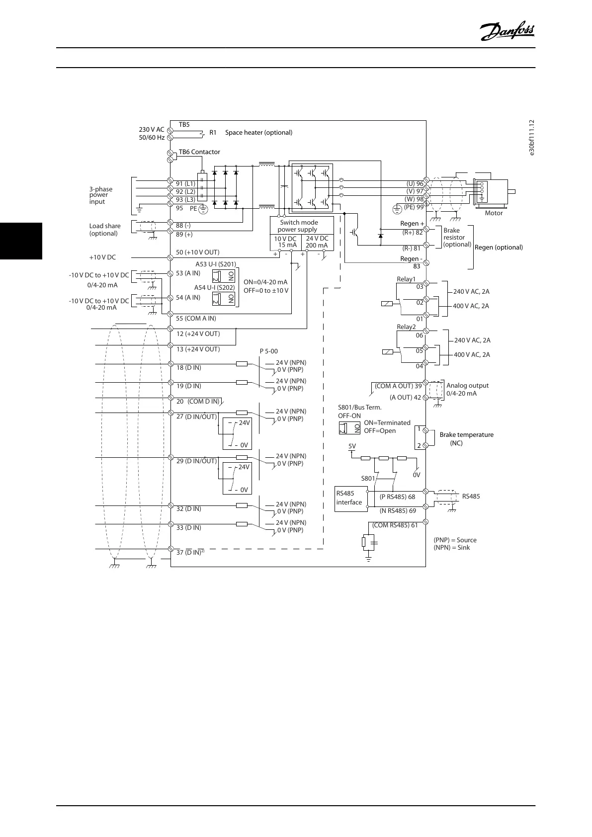
5.3 Wiring Schematic
e30bf111.12
230 V AC
50/60 Hz
TB5
R1
Regen +
Regen -
83
Regen (optional)
1
2
Brake temperature
(NC)
Space heater (optional)
91 (L1)
92 (L2)
93 (L3)
PE
88 (-)
89 (+)
50 (+10 V OUT)
53 (A IN)
54 (A IN)
55 (COM A IN)
0/4-20 mA
12 (+24 V OUT)
13 (+24 V OUT)
18 (D IN)
20
(COM D IN)
15 mA
200 mA
(U) 96
(V) 97
(W) 98
(PE) 99
(COM A OUT) 39
(A OUT) 42
0/4-20 mA
03
+10 V DC
-10 V DC to +10 V DC
0/4-20 mA
24 V DC
02
01
05
04
06
240 V AC, 2A
24 V (NPN)
0 V (PNP)
0 V (PNP)
24 V (NPN)
19 (D IN)
24 V (NPN)
0 V (PNP)
27
24V
0V
(D IN/OUT)
0 V (PNP)
24 V (NPN)
(D IN/OUT)
0V
24V
29
24 V (NPN)
0 V (PNP)
0 V (PNP)
24 V (NPN)
33 (D IN)
32 (D IN)
1
2
ON
A53 U-I (S201)
ON
2
1
A54 U-I (S202)
ON=0/4-20 mA
OFF=0 to ±10 V
95
400 V AC, 2A
P 5-00
(R+) 82
(R-) 81
37 (D IN)
2)
+
-
+
-
(P RS485) 68
(N RS485) 69
(COM RS485) 61
0V
5V
S801
RS485
RS485
2
1
ON
S801/Bus Term.
OFF-ON
3-phase
power
input
Load share
Switch mode
power supply
Motor
Analog output
interface
Relay1
Relay2
ON=Terminated
OFF=Open
Brake
resistor
(NPN) = Sink
(PNP) = Source
=
=
=
240 V AC, 2A
400 V AC, 2A
-10 V DC to +10 V DC
10 V DC
(optional)
(optional)
TB6 Contactor
1)
Illustration 5.2 Basic Wiring Schematic
1) TB6 contactor is found only in D6h and D8h drives with a contactor option.
2) Terminal 37 (optional) is used for Safe Torque O. Refer to the VLT
®
FC Series - Safe Torque O Operating Guide for installation
instructions.
Electrical Installation VLT® AQUA Drive FC 202
26 Danfoss A/S © 09/2018 All rights reserved. MG21A502
55

Table of Contents

Other manuals for Danfoss VLT AQUA Drive FC 202

Related product manuals