4.7 Mounting the Drive
Depending on the drive model and conguration, the
drive can oor-mounted or wall-mounted.
Drive models D1h–D2h and D5h–D8h can be
oor
mounted. Floor-mounted drives require space below the
drive for airow. To provide this space, the drives can be
mounted on a pedestal. The D7h and D8h drives come
with a standard pedestal. Optional pedestal kits are
available for other D-sized drives.
Drives in enclosure sizes D1h–D6h can be wall-mounted.
Drive models D3h and D4h are P20/Chassis drives, which
can be mounted on a wall or on a mounting plate within a
cabinet.
Creating cable openings
Before attaching the pedestal or mounting the drive,
create cable openings in the gland plate and install it at
the bottom of the drive. The gland plate provides access
for AC mains and motor cable entry while maintaining
IP21/IP54 (Type 1/Type 12) protection ratings. For gland
plate dimensions, see chapter 10.9 Enclosure Dimensions.
•
If the gland plate is a metal plate, punch cable
entry holes in the plate with a sheet metal
punch. Insert cable
ttings into the holes. See
Illustration 4.4.
•
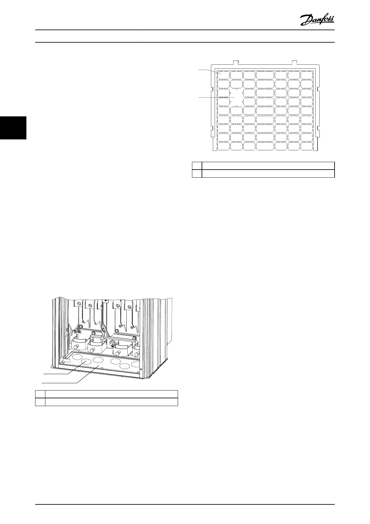
If the gland plate is plastic, punch out plastic tabs
to accommodate the cables. See Illustration 4.5.
1 Cable entry hole
2 Metal gland plate
Illustration 4.4 Cable Openings in Sheet Metal Gland Plate
1 Plastic tabs
2 Tabs removed for cable access
Illustration 4.5 Cable Openings in Plastic Gland Plate
Attaching the drive to the pedestal
To install a standard pedestal, use the following steps. To
install an optional pedestal kit, refer to the instructions
that shipped with the kit. See Illustration 4.6.
1. Unfasten 4 M5 screws, and remove the pedestal
front cover plate.
2. Secure 2 M10 nuts over the threaded studs at the
back of the pedestal, securing it to the drive back
channel.
3. Fasten 2 M5 screws through the back ange of
the pedestal into the pedestal mounting bracket
on the drive.
4. Fasten 4 M5 screws through the front ange of
the pedestal and into the gland plate mounting
holes.
Mechanical Installation VLT® AQUA Drive FC 202
20 Danfoss A/S © 09/2018 All rights reserved. MG21A502
44

 Loading...


