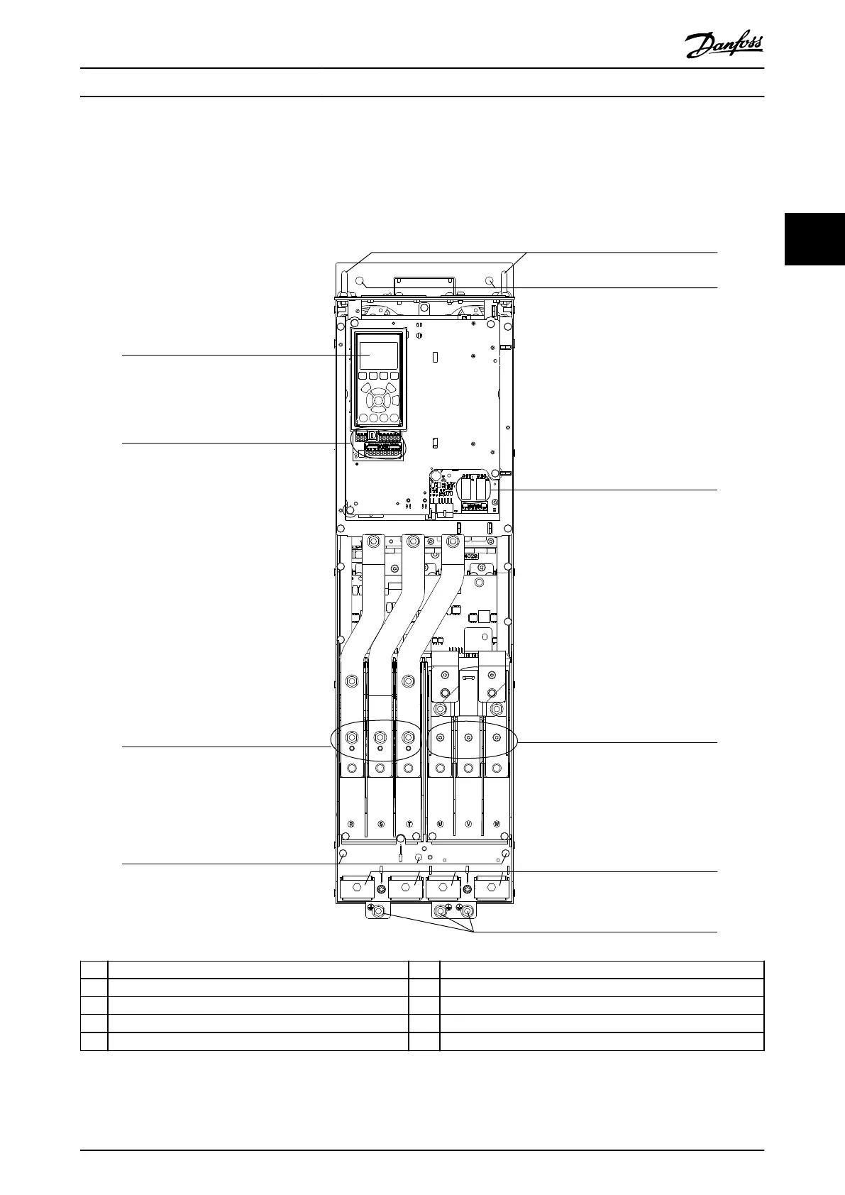
3.3 Interior View of D1h Drive
Illustration 3.1 shows the D1h components relevant to installation and commissioning. The D1h drive interior is similar to
that of the D3h, D5h, and D6h drives. Drives with the contactor option also contain a contactor terminal block (TB6). For the
location of TB6, see chapter 5.8 Terminal Dimensions.
1 LCP (local control panel) 6 Mounting holes
2 Control terminals 7 Relays 1 and 2
3 Mains input terminals 91 (L1), 92 (L2), 93 (L3) 8 Motor output terminals 96 (U), 97 (V), 98 (W)
4 Ground terminals for IP21/54 (Type 1/12) 9 Cable clamps
5 Lifting ring 10 Ground terminals for IP20 (Chassis)
Illustration 3.1 Interior View of D1h Drive (similar to D3h/D5h/D6h)
Product Overview Operating Guide
MG21A502 Danfoss A/S © 09/2018 All rights reserved. 9
3 3

 Loading...


