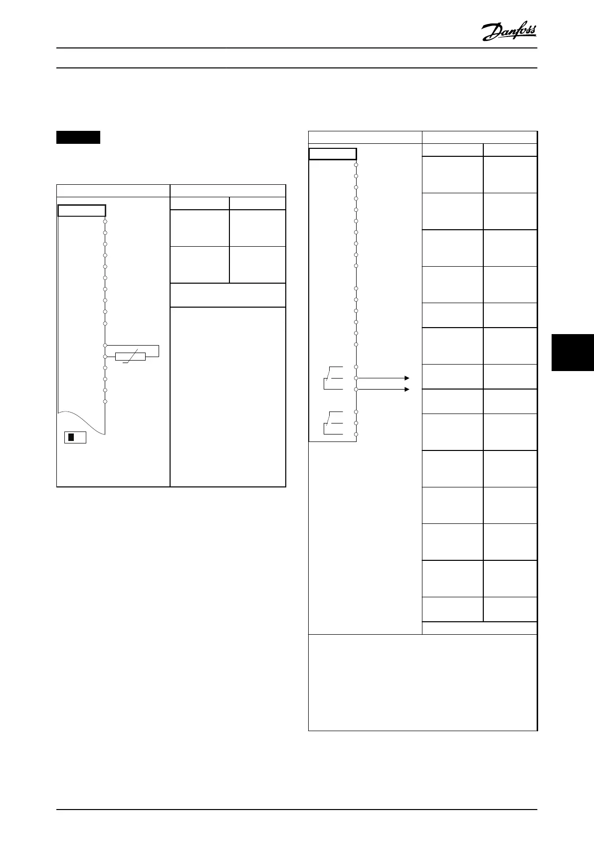
8.8 Wiring Conguration for a Motor
Thermistor
NOTICE
Thermistors must use reinforced or double insulation to
meet PELV insulation requirements.
Parameters
130BB686.12
VLT
+24 V
+24 V
D IN
D IN
D IN
COM
D IN
D IN
D IN
+10 V
A IN
A IN
COM
A OUT
COM
12
13
18
19
20
27
29
32
33
50
53
54
55
42
39
A53
U - I
D IN
37
Function Setting
Parameter 1-90
Motor Thermal
Protection
[2] Thermistor
trip
Parameter 1-93
Thermistor
Source
[1] analog
input 53
*=Default value
Notes/comments:
If only a warning is wanted, set
parameter 1-90 Motor Thermal
Protection to [1] Thermistor
warning.
Table 8.12 Wiring Conguration for a Motor Thermistor
8.9
Wiring Conguration for a Relay Set-up
with Smart Logic Control
Parameters
FC
+24 V
+24 V
D IN
D IN
D IN
COM
D IN
D IN
D IN
D IN
+10 V
A IN
A IN
COM
A OUT
COM
R1R2
12
13
18
19
20
27
29
32
33
37
50
53
54
55
42
39
01
02
03
04
05
06
130BB839.10
Function Setting
Parameter 4-30
Motor Feedback
Loss Function
[1] Warning
Parameter 4-31
Motor Feedback
Speed Error
100 RPM
Parameter 4-32
Motor Feedback
Loss Timeout
5 s
Parameter 7-00 S
peed PID
Feedback Source
[2] MCB 102
Parameter 17-11
Resolution (PPR)
1024*
Parameter 13-00
SL Controller
Mode
[1] On
Parameter 13-01
Start Event
[19] Warning
Parameter 13-02
Stop Event
[44] Reset key
Parameter 13-10
Comparator
Operand
[21] Warning
no.
Parameter 13-11
Comparator
Operator
[1] ≈ (equal)*
Parameter 13-12
Comparator
Value
90
Parameter 13-51
SL Controller
Event
[22]
Comparator 0
Parameter 13-52
SL Controller
Action
[32] Set digital
out A low
Parameter 5-40 F
unction Relay
[80] SL digital
output A
*=Default value
Notes/comments:
If the limit in the feedback monitor is exceeded, warning 90,
Feedback Mon. is issued. The SLC monitors warning 90, Feedback
Mon. and if the warning becomes true, relay 1 is triggered.
External equipment may require service. If the feedback error
goes below the limit again within 5 s, the drive continues and
the warning disappears. Reset relay 1 by pressing [Reset] on the
LCP.
Table 8.13 Wiring Conguration for a Relay Set-up with
Smart Logic Control
Wiring Conguration Exampl... Operating Guide
MG21A502 Danfoss A/S © 09/2018 All rights reserved. 77
8 8

 Loading...


