•
•
•
•
•
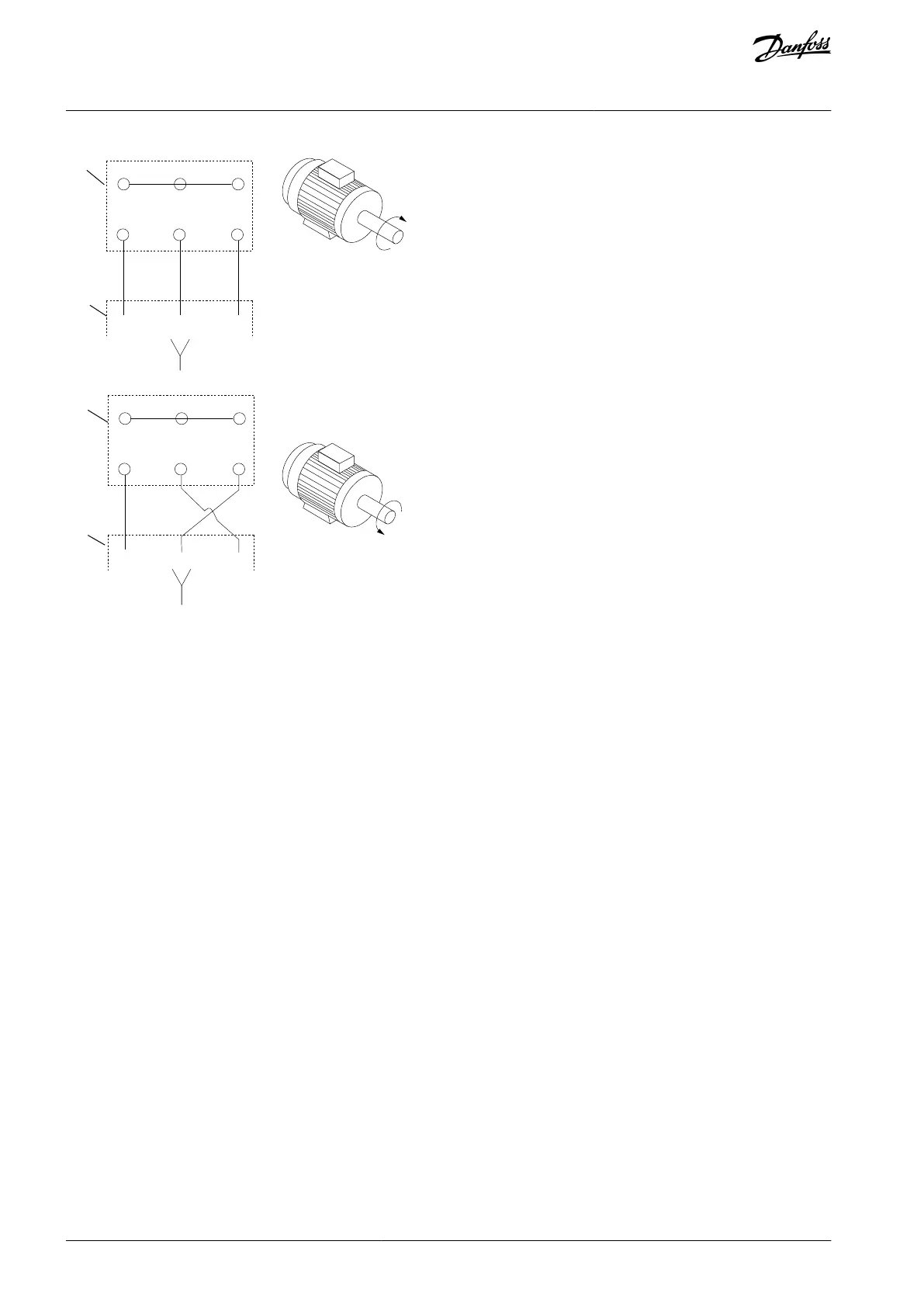
Illustration 72: Terminal Connection for Clockwise and Counterclockwise Rotation
Change direction of rotation by switching 2 phases in the motor cable or by changing the setting of parameter 4-10 Motor Speed
Direction. Check the motor rotation in parameter 1-28 Motor Rotation Check and follow the steps in the display.
10.8.1 Motor Thermal Protection
The electronic thermal relay in the drive has received UL approval for single motor overload protection.
For motor thermal protection, it is also possible to use the VLT® PTC Thermistor Card MCB 112 option card. This card provides ATEX
certication to protect motors in explosion hazardous areas Zone 1/21 and Zone 2/22. Combining ATEX ETR with the use of MCB
112 enables control of an Ex-e or EX-n motor in explosion hazardous ares.
Consult the Programming Guide for details on how to set up the drive for safe operation of Ex-e or Ex-n motors.
10.8.2 Parallel Connection of Motors
The drive can control several parallel-connected motors. When using parallel motor connection, observe the following:
Recommended to run applications with parallel motors in U/F mode parameter 1-01 Motor Control Principle [0]. Set the U/F graph
in parameter 1-55 U/f Characteristic - U and parameter 1-56 U/f Characteristic - F.
VCC
+
mode may be used in some applications.
The total current consumption of the motors must not exceed the rated output current I
INV
for the drive.
If motor sizes are widely dierent in winding resistance, starting problems may occur due to too low motor voltage at low
speed.
The electronic thermal relay (ETR) of the drive cannot be used as motor overload protection for the individual motor. Provide
further motor overload protection by including thermistors in each motor winding or individual thermal relays.
AJ300847815559en-000101 / 130R0337136 | Danfoss A/S © 2020.09
Electrical Installation
Considerations
VLT® AQUA Drive FC 202
Design Guide

 Loading...


