2.
3.
4.
5.
6.
7.
8.
9.
10.
11.
12.
13.
14.
tramp =
tacc × nnorm par . 1 − 25
ref RPM
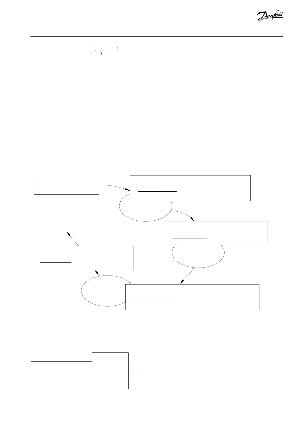
In parameter 5-12 Terminal 27 Digital Input, set terminal 27 to [0] No Operation.
Set preset reference 0 to 1
st
preset speed (parameter 3-10 Preset Reference [0] in percentage of maximum reference speed
(parameter 3-03 Maximum Reference). Example: 60%.
Set preset reference 1 to 2
nd
preset speed (parameter 3-10 Preset Reference [1]. Example: 0%.
Set the timer 0 for constant running speed in parameter 13-20 SL Controller Timer [0]. Example: 2 s.
Set Event 1 in parameter 13-51 SL Controller Event [1] to [1] True.
Set Event 2 in parameter 13-51 SL Controller Event [2] to [4] On Reference.
Set Event 3 in parameter 13-51 SL Controller Event [3] to [30] Time Out 0.
Set Event 4 in parameter 13-51 SL Controller Event [4] to [0] False.
Set Action 1 in parameter 13-52 SL Controller Action [1] to [10] Select preset 0.
Set Action 2 in parameter 13-52 SL Controller Action [2] to [29] Start Timer 0.
Set Action 3 in parameter 13-52 SL Controller Action [3] to [11] Select preset 1.
Set Action 4 in parameter 13-52 SL Controller Action [4] to [1] No Action.
Set the SLC in parameter 13-00 SL Controller Mode to [1] On.
A start/stop command is applied on terminal 18. If the stop signal is applied, the drive ramps down and goes into free mode.
Event 1 True (1)
Action 1 Select Preset (10)
State 2
State 1
Event 2 On Reference (4)
Action 2 Start Timer (29)
Action 3 Select Preset ref. (11)
e30ba148.12
Illustration 38: SLC Application Example
6.2.12.4 RS Flip Flops
The reset/set ip ops hold the signal until set/reset.
Parameter 13-15
RS-FF Operand S
Parameter 13-16
RS-FF Operand R
e30bb959.11
Illustration 39: Reset/set Flip Flops
AJ300847815559en-000101 / 130R0337 | 51Danfoss A/S © 2020.09
Product Features
VLT® AQUA Drive FC 202
Design Guide

 Loading...


