e75ha208.10
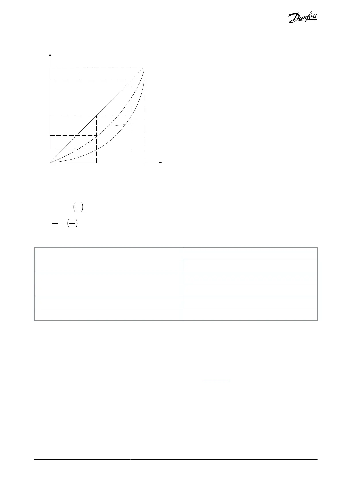
P o w er ~n
3
P r essur e ~n
2
Illustration 7: Anity Laws for Centrifugal Pumps
Flow:
Q1
Q2
=
n1
n2
Pressure:
H1
H2
=
n1
n2
2
Power:
P1
P2
=
n1
n2
3
Assuming an equal eciency in the speed range.
Anity Laws
Q
2
=Reduced ow (or increased ow)
P
2
=Reduced power (or increased power)
H
2
=Reduced pressure (or increased pressure)
n
2
=Reduced speed (or reduced speed)
4.3.2 Valve Control versus Speed Control of Centrifugal Pumps
Valve control
As the demand for process requirements in water systems varies, the ow to be adjusted accordingly. Frequently used methods for
ow adaptation are throttling or recycling using valves. A recycle valve that is opened too wide can cause the pump to run at the
end of the pump curve with a high ow rate at a low pump head. These conditions do not only cause a waste of energy due to the
high speed of the pump, but can also lead to pump cavitation resulting in pump damage.
Throttling the ow with a valve adds a pressure drop across the valve (HP-HS). This can be compared with accelerating and pulling
the brake at the same time in an attempt to reduce the car speed. As shown in Illustration 8, throttling makes the system curve turn
from point (2) on the pump curve to a point with signicantly reduced eciency (1).
AJ300847815559en-000101 / 130R0337 | 23Danfoss A/S © 2020.09
Product Family Overview
VLT® AQUA Drive FC 202
Design Guide

 Loading...


