EasyManua.ls Logo

Danfoss VLT AQUA FC 202 - 3.3.4 Terminal Locations - E Enclosures

Danfoss VLT AQUA FC 202
218 pages
Print Icon
To Next Page IconTo Next Page
To Previous Page IconTo Previous Page
Loading...
e75ha209.11
60
50
40
30
20
10
H
s
0
100
200 300 400
(m w g)
B
C
A
750r pm
1050r pm
1350r pm
1650r pm
0
10
20
30
(kW
)
40
50
60
200
100
300 ( m
3
/h )
( m
3
/h )
400
750r
pm
1050r pm
1350r pm
1650r pm
P
shaf
t
C
1
B
1
A
1
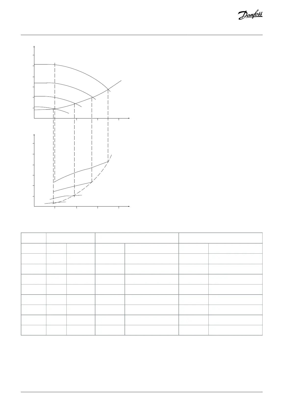
Illustration 12: Energy
Table 9: Result
m
3
/h
Distribution
Valve regulation
Drive control
%
Hours
Power
Consumption
Power
Consumption
A
1
- B
1
kWh
A
1
- C
1
kWh
350
5
438
42.5
18.615
42.5
18.615
300
15
1314
38.5
50.589
29.0
38.106
250
20
1752
35.0
61.320
18.5
32.412
200
20
1752
31.5
55.188
11.5
20.148
150
20
1752
28.0
49.056
6.5
11.388
100
20
1752
23.0
40.296
3.5
6.132
Σ
100
8760
–
275.064
–
26.801
4.3.4 Improved Control
Using a drive to control the ow or pressure of a system improves control. A drive can vary the speed of the fan or pump, obtaining
variable control of ow and pressure. Furthermore, a drive can quickly adapt the speed of the fan or pump to new ow or pressure
conditions in the system.
Obtain simple control of process (ow, level, or pressure) using the built-in PI control.
AJ300847815559en-000101 / 130R033726 | Danfoss A/S © 2020.09
Product Family Overview
VLT® AQUA Drive FC 202
Design Guide

Table of Contents

Other manuals for Danfoss VLT AQUA FC 202

Related product manuals