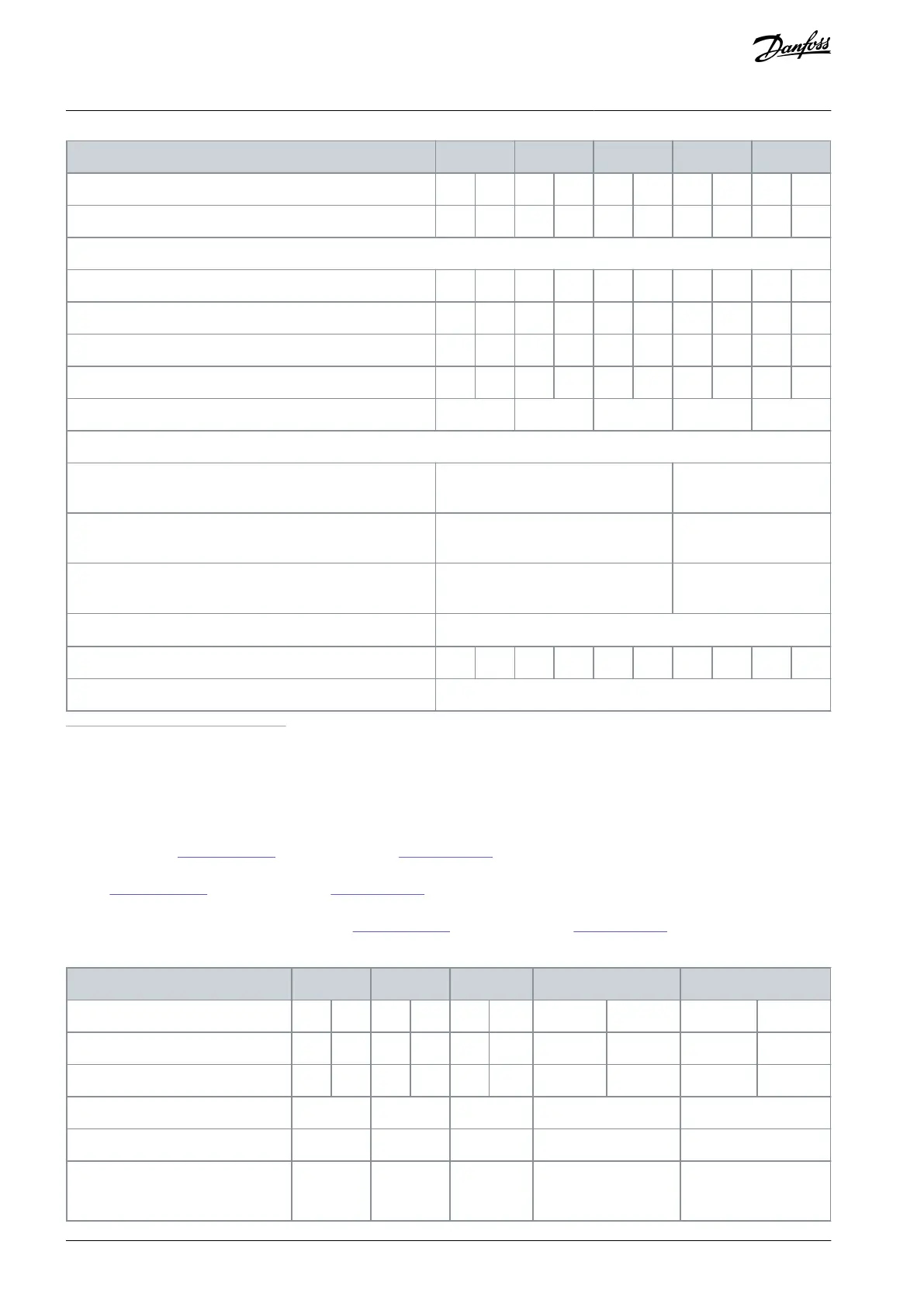
Continuous kVA at 400 V [kVA]
Continuous kVA at 460 V [kVA]
Continuous (3x380–440 V) [A]
Intermittent (60 s overload) (3x380–440 V) [A]
Continuous (3x441–480 V) [A]
Intermittent (60 s overload) (3x441–480 V) [A]
Protection ratings IP21, IP55, IP66 maximum cable cross-sec-
tion
(3)
for mains, brake, and load sharing [mm
2
(AWG)]
Protection ratings IP21, IP55, IP66 maximum cable cross-sec-
tion
(3)
for motor [mm
2
(AWG)]
Protection rating IP20 maximum cable cross-section
(3)
for
mains, brake, motor, and load sharing [mm
2
(AWG)]
Maximum cable cross-section
(3)
for disconnect [mm
2
(AWG)]
Estimated power loss
(4)
at rated maximum load [W]
(5)
1
High overload=150% or 160% torque for a duration of 60 s. Normal overload=110% torque for a duration of 60 s.
2
Enclosure sizes B3+B4 and C3+C4 can be converted to IP21 using a conversion kit. See also chapters Mechanical mounting and IP21/Type 1 Enclo-
sure kit in the design guide.
3
The 3 values for the maximum cable cross-section are for single core, exible wire, and exible wire with sleeve, respectively.
4
Applies for dimensioning of drive cooling. If the switching frequency is higher than the default setting, the power losses may increase. LCP and
typical control card power consumptions are included. For more detailed eciency values and part load losses according IEC/EN 61800-9-2 refer to
mydrive ecosmart on
www. danfoss.com. For eciency class see 8.4.1 Environment.
5
Eciency measure at nominal current. For more detailed eciency values and part load losses according IEC/EN 61800-9-2 refer to mydrive ecos-
mart on
www. danfoss.com. For eciency class see 8.4.1 Environment.
6
Measured using 5 m (16 ft) shielded motor cables at rated load and rated frequency. For more detailed eciency values and part load losses ac-
cording IEC/EN 61800-9-2 refer to mydrive ecosmart on
www. danfoss.com. For eciency class see 8.4.1 Environment.
Table 34: Mains Supply 3x380–480 V AC, P37K–P90K
Typical shaft output [kW]
Typical shaft output at 460 V [hp]
Protection rating IP20/Chassis
(2)
Protection rating IP21/Type 1
Protection rating IP55/Type 12
Protection rating IP66/NEMA 4X
AJ300847815559en-000101 / 130R033780 | Danfoss A/S © 2020.09
Specications
VLT® AQUA Drive FC 202
Design Guide

 Loading...


