EasyManuals Logo

Danfoss VLT AQUA FC 202 Design Guide

Danfoss VLT AQUA FC 202
218 pages
To Next Page IconTo Next Page
To Previous Page IconTo Previous Page
Page #62 background imageLoading...
Page #62 background image
B
A
E
C
D
e30bt324.10
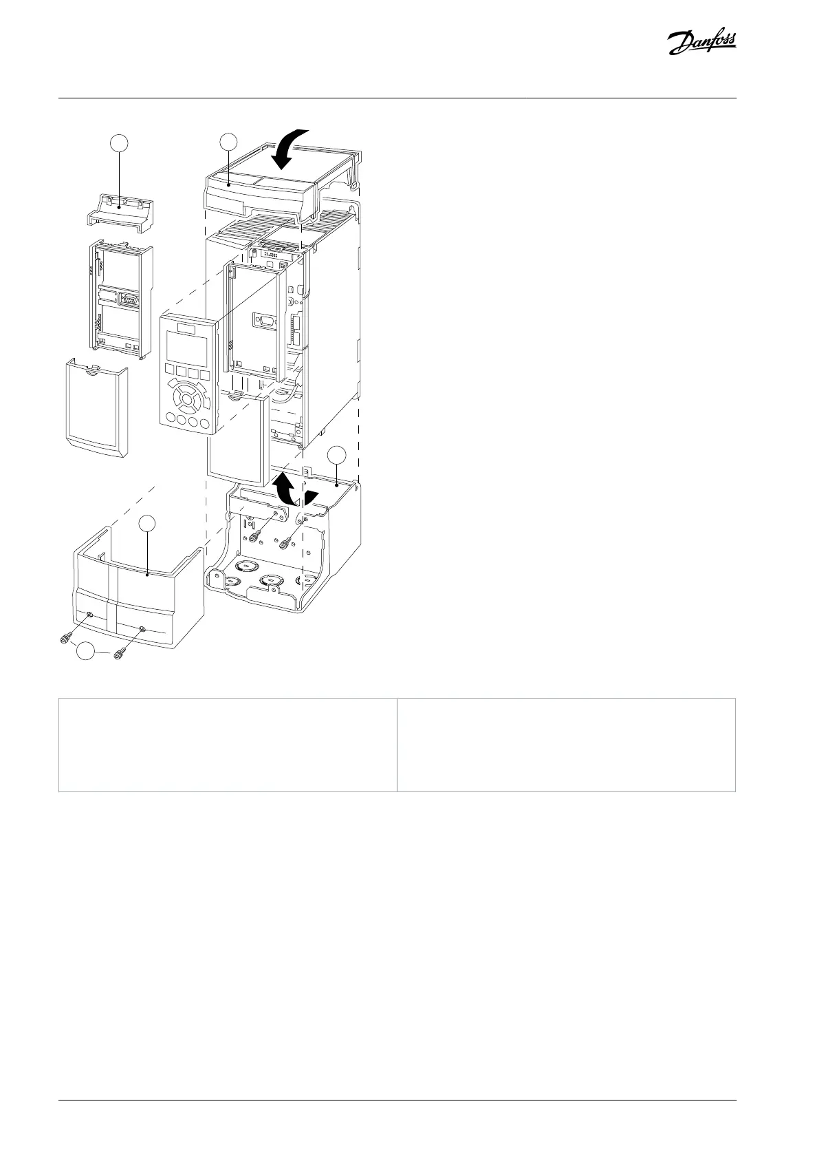
Illustration 44: IP21/Nema Type 1 Kit on A3 Enclosure
A
Top cover
B
Brim
C
Base part
D
Base cover
E
Screw(s)
Place the top cover as shown. If an A or B option is used, t the brim to cover the top inlet. Place the base part C at the bottom of the
drive and use the clamps from the accessory bag to correctly fasten the cables.
Holes for cable glands:
Enclosure size A2: 2x M25 and 3xM32.
Enclosure size A3: 3xM25 and 3xM32.
AJ300847815559en-000101 / 130R033762 | Danfoss A/S © 2020.09
Options and Accessories Overview
VLT® AQUA Drive FC 202
Design Guide

Table of Contents

Other manuals for Danfoss VLT AQUA FC 202

Questions and Answers:

Question and Answer IconNeed help?

Do you have a question about the Danfoss VLT AQUA FC 202 and is the answer not in the manual?

Danfoss VLT AQUA FC 202 Specifications

General IconGeneral
BrandDanfoss
ModelVLT AQUA FC 202
CategoryDC Drives
LanguageEnglish

Related product manuals