•
•
•
•
•
•
•
•
•
Indicators for alarms and warnings are visible through the cover.
Can be mounted on a wall from 0.1–90 mm thickness.
The kit contains the following parts (see 13.2.7 Order Numbers for Local Control Panel Options):
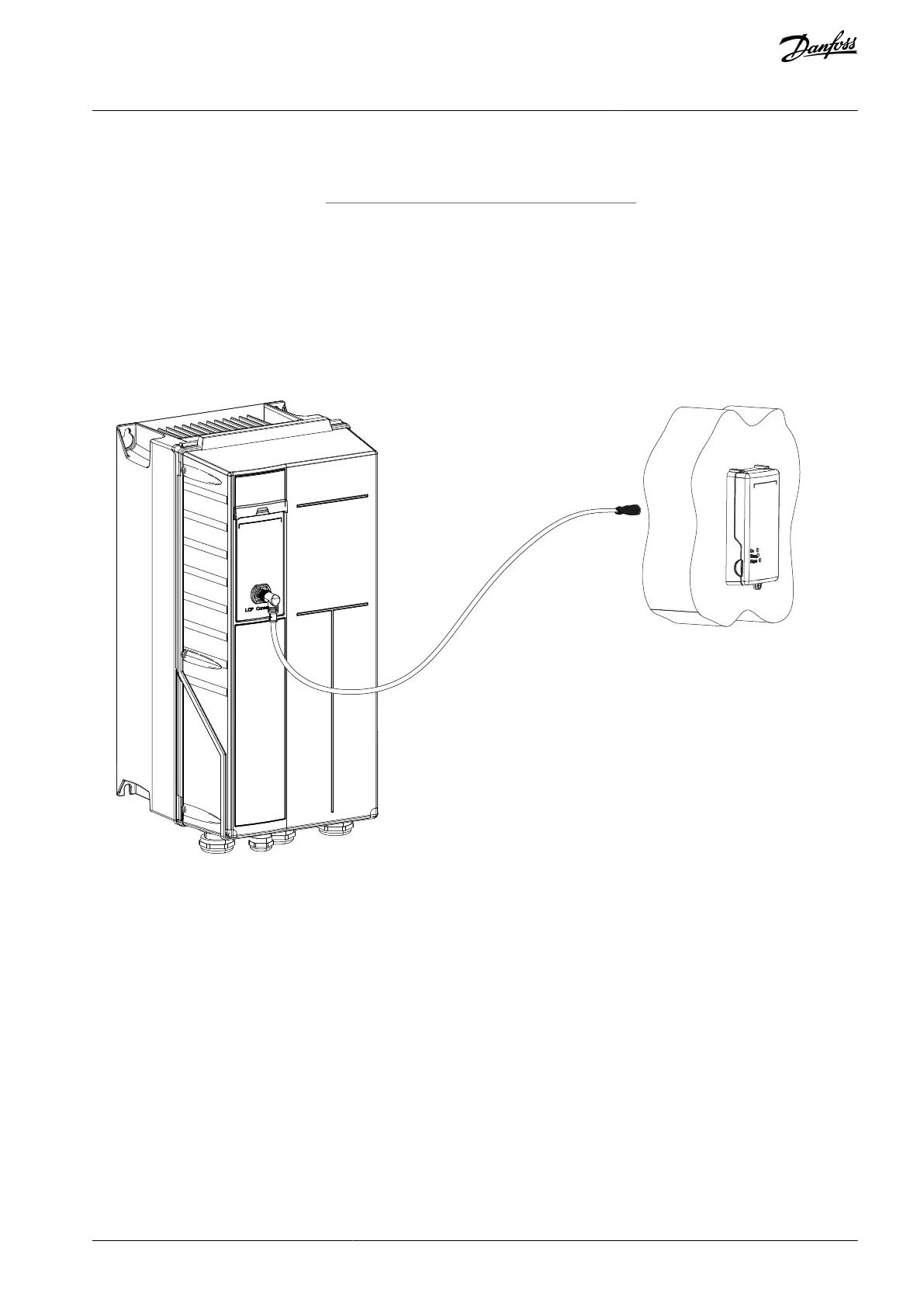
LCP cables with 2 M12 connectors (90° male connector and straight female connector).
Cable to the LCP.
Blind cover with M12 female connector.
Base plate with D-sub connector and M12 male connector.
Two gaskets and 1 nut for the D-sub connector.
Intermediate cover with the front cover.
Disassembly tool.
Illustration 48: Remote Connection of the LCP
AJ300847815559en-000101 / 130R0337 | 67Danfoss A/S © 2020.09
Options and Accessories Overview
VLT® AQUA Drive FC 202
Design Guide

 Loading...


