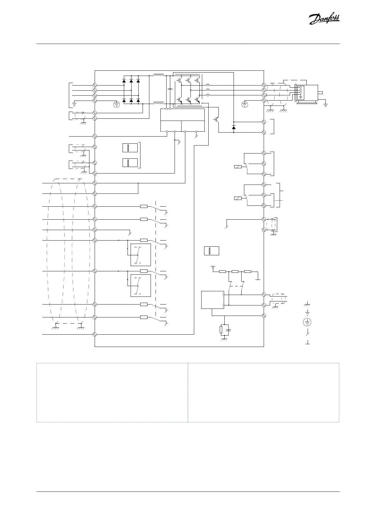
4.4 Wiring Schematic
––
Motor
Analog Output
ON=Terminated
OFF=Open
A IN)
37 (D IN)
1)
18 (D IN)
+ - + -
(U) 96
(V) 97
(W) 98
(PE) 99
(P RS485) 68
(N RS485) 69
0 V
5V
S801
0/4–20 mA
RS-485
03
240 V AC, 2 A
24 V DC
02
01
05
04
06
24
V (NPN)
33 (D IN)
32 (D IN)
S202
ON=0/4–20 mA
95
P 5-00
21
ON
S801
(R+) 82
(R-) 81
: Chassis
240 V AC, 2 A
400 V AC, 2 A
: PE
50 (+10 V OUT)
55 (COM A IN)
12 (+24 V OUT)
13 (+24 V OUT)
20 (COM D IN)
Switch mode
power supply
Brake
resistor
Relay 1
Relay 2
(COM A OUT) 39
(A OUT) 42
: Ground
: Ground 1
: Ground 2
(COM RS485) 61
OFF=0/-10 V DC
to +10 V DC
Illustration 6: Basic Wiring Schematic
Terminal 37 (optional) is used for Safe Torque Off
(STO). For installation instructions, refer to the VLT
®
Safe Torque Off Operating Guide. For FC 301, termi-
nal 37 is only included in enclosure size A1. Relay 2
and terminal 29 have no function in FC 301.
Do not connect cable shield.
Read more in EMC-Compliant Installation.
AQ267037727118en-000101 / 130R0300 | 17Danfoss A/S © 2021.01
Electrical Installation
VLT® AutomationDrive FC 301/FC 302
Operating Guide

 Loading...


