•
•
1.
2.
3.
4.
•
•
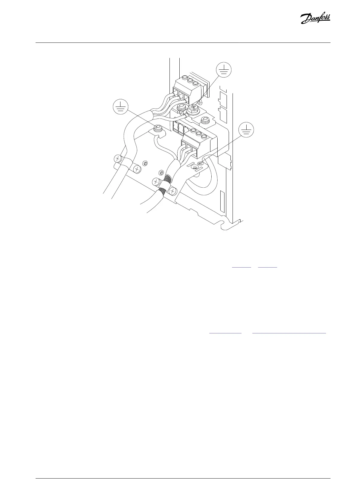
Illustration 7: Example of Motor, Mains, and Ground Wiring
4.6 Connecting AC Mains
Size the wiring based on the input current of the drive. For maximum wire sizes, see Table 29 to Table 40.
Comply with local and national electrical codes for cable sizes.
4.6.1 Connecting the Drive to Mains
Procedure
Connect the 3-phase AC input power wiring to terminals L1, L2, and L3.
Depending on the configuration of the equipment, connect the input power to the mains input terminals or the input dis-
connect.
Ground the cable in accordance with the grounding instructions, see 4.3 Grounding and 4.5.1 Grounding the Cable Shield.
When supplied from an isolated mains source (IT mains or floating delta) or TT/TN-S mains with a grounded leg (grounded
delta), ensure that parameter 14-50 RFI Filter is set to [0] Off. This setting prevents damage to the DC link and reduces
ground capacity currents in accordance with IEC 61800-3.
4.7 Control Wiring
Isolate the control wiring from the high-power components in the drive.
When the drive is connected to a thermistor, enusre that the thermistor control wiring is shielded and reinforced/double insula-
ted. A 24 V DC supply voltage is recommended.
4.7.1 Safe Torque Off (STO)
To run STO, additional wiring for the drive is required.
Refer to the VLT® Frequency Converters Safe Torque Off Operating Guide for further information.
AQ267037727118en-000101 / 130R0300 | 19Danfoss A/S © 2021.01
Electrical Installation
VLT® AutomationDrive FC 301/FC 302
Operating Guide

 Loading...


