•
•
•
•
•
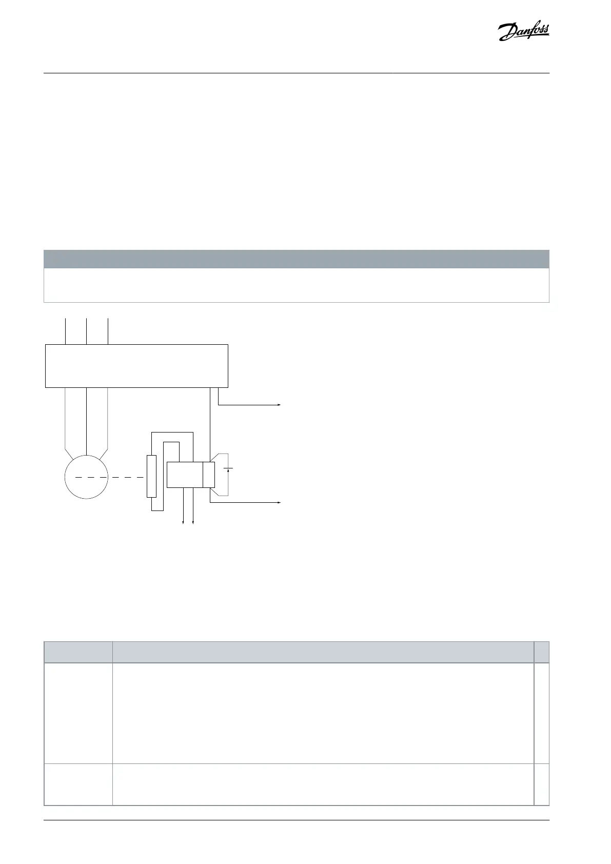
4.7.2 Mechanical Brake Control
In hoisting/lowering applications, it is necessary to control an electro-mechanical brake.
Control the brake using any relay output or digital output (terminal 27 or 29).
Keep the output closed (voltage-free) as long as the drive is unable to keep the motor at standstill, for example due to the load
being too heavy.
Select [32] Mechanical brake control in parameter group 5-4* Relays for applications with an electromechanical brake.
The brake is released when the motor current exceeds the value in parameter 2-20 Release Brake Current.
The brake is engaged when the output frequency is less than the frequency set in parameter 2-21 Activate Brake Speed [RPM] or
parameter 2-22 Activate Brake Speed [Hz], and only if the drive carries out a stop command.
If the drive is in alarm mode or in an overvoltage situation, the mechanical brake immediately closes.
N O T I C E
The drive is not a safety device. It is the responsibility of the system designer to integrate safety devices according to relevant
national crane/lift regulations.
e30ba902.11
L1 L2 L3
U V W
02 01
A1
A2
Drive
Output
relay
Command circuit
220 V AC
Mechanical
brake
Shaft
Motor
Frewheeling
diode
Brake
380 V AC
Output
contactor
input
power circuit
Illustration 8: Connecting the Mechanical Brake to the Drive
4.8 Installation Check List
Before completing installation of the unit, inspect the entire installation as detailed in the following table. Check and mark the items
when completed.
Table 5: Installation Check List
Look for auxiliary equipment, switches, disconnects, or input fuses/circuit breakers residing on the in-
put power side of the drive, or output side to the motor. Ensure that they are ready for full-speed oper-
ation.
Check the function and installation of any sensors used for feedback to the drive.
Remove any power factor correction capacitors on the motor.
Adjust any power factor correction capacitors on the mains side and ensure that they are dampened.
Ensure that the motor wiring and control wiring are separated, shielded, or in 3 separate metallic con-
duits for high-frequency interference isolation.
AQ267037727118en-000101 / 130R030020 | Danfoss A/S © 2021.01
Electrical Installation
VLT® AutomationDrive FC 301/FC 302
Operating Guide
 Loading...


