EasyManuals Logo
Home>Danfoss>DC Drives>VLT AutomationDrive FC 301

Danfoss VLT AutomationDrive FC 301 Operating Guide

Danfoss VLT AutomationDrive FC 301
92 pages
To Next Page IconTo Next Page
To Previous Page IconTo Previous Page
Page #33 background imageLoading...
Page #33 background image
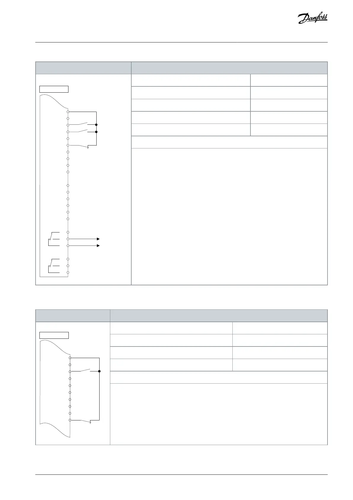
Table 18: Run Permissive
Parameter
+24 V
+24 V
D IN
D IN
D IN
COM
D IN
D IN
D IN
D IN
+10
V
A IN
A IN
COM
A OUT
COM
R1
R2
12
13
18
19
20
27
29
32
33
37
50
53
54
55
42
39
01
02
03
04
05
06
e30bb684.11
Drive
Function
Setting
Parameter 5-10 Terminal 18 Digital Input
[8] Start*
Parameter 5-11 Terminal 19 Digital Input
[52] Run permissive
Parameter 5-12 Terminal 27 Digital Input
[7] External interlock
Parameter 5-40 Function Relay
[167] Start command act.
*=Default value
Notes/comments:
D IN 37 is an option.
6.1.7 Wiring Configuration: Start/Stop
Table 19: Start/Stop Command with Safe Torque Off Option
Parameter
+24 V
+24 V
D IN
D IN
D IN
COM
D IN
D IN
D IN
D IN
12
13
18
19
20
27
29
32
33
37
e30bb802.12
Drive
Function
Setting
Parameter 5-10 Terminal 18 Digital Input
[Start]*
Parameter 5-12 Terminal 27 Digital Input
[0] No operation
Parameter 5-19 Terminal 37 Safe Stop
[1] Safe Stop Alarm
*=Default value
Notes/comments:
If parameter 5-12 Terminal 27 Digital Input is set [0] No operation, a jumper wire to terminal 27 is
not needed.
D IN 37 is an option.
AQ267037727118en-000101 / 130R0300 | 33Danfoss A/S © 2021.01
Basic I/O Configuration
VLT® AutomationDrive FC 301/FC 302
Operating Guide

Table of Contents

Other manuals for Danfoss VLT AutomationDrive FC 301

Questions and Answers:

Question and Answer IconNeed help?

Do you have a question about the Danfoss VLT AutomationDrive FC 301 and is the answer not in the manual?

Danfoss VLT AutomationDrive FC 301 Specifications

General IconGeneral
BrandDanfoss
ModelVLT AutomationDrive FC 301
CategoryDC Drives
LanguageEnglish

Related product manuals