•
•
•
•
•
•
•
•
•
•
•
6 Basic I/O Configuration
6.1 Application Examples
The examples in this section are intended as a quick reference for common applications.
Parameter settings are the regional default values unless otherwise indicated (selected in parameter 0-03 Regional Settings).
Parameters associated with the terminals and their settings are shown next to the drawings.
Required switch settings for analog terminals A53 or A54 are also shown.
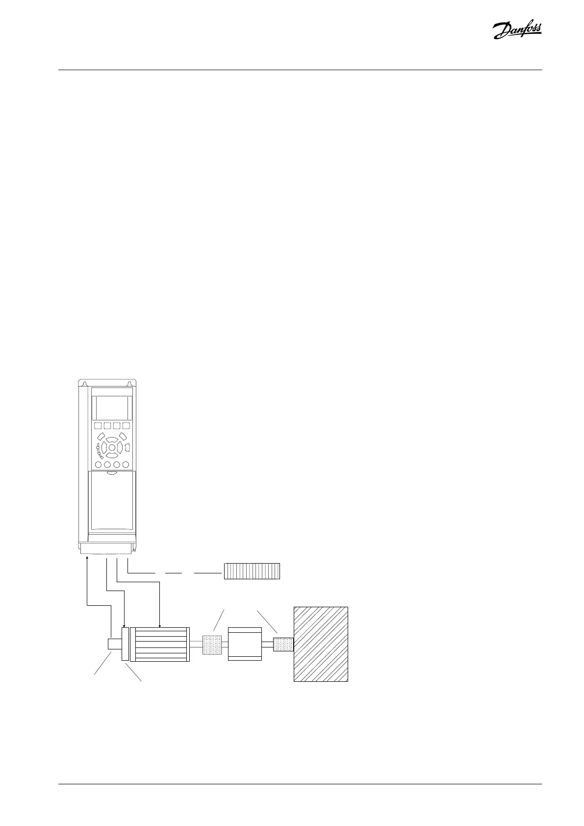
6.1.1 Programming a Closed-loop Drive System
A closed-loop drive system usually consists of:
Motor.
Drive.
Encoder (as feedback system).
Mechanical brake.
Brake resistor (for dynamic braking).
Transmission.
Gear box.
Load.
Applications demanding mechanical brake control typically need a brake resistor.
e30bt865.10
Encoder
Mechanical brake
Motor
Gearbox
Load
Transmission
Brake resistor
Illustration 10: Basic Set-up for Closed-loop Speed Control
AQ267037727118en-000101 / 130R0300 | 25Danfoss A/S © 2021.01
Basic I/O Configuration
VLT® AutomationDrive FC 301/FC 302
Operating Guide

 Loading...


