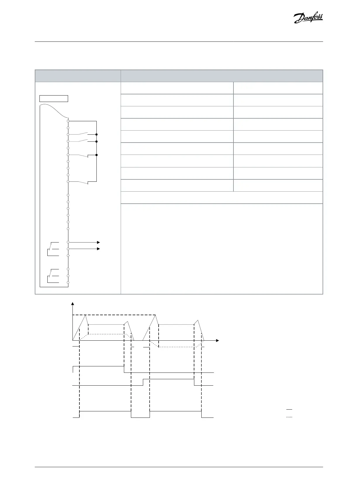
6.1.13 Wiring Configuration: Mechanical Brake Control
Table 27: Mechanical Brake Control
+24 V
+24 V
D IN
D IN
D IN
COM
D IN
D IN
D IN
D IN
+10
R 1 R 2
12
13
18
19
20
27
29
32
33
50
53
54
55
42
39
01
02
03
04
05
06
e30bb841.10
Parameter 5-10 Terminal 18 Digital Input
Parameter 5-11 Terminal 19 Digital Input
Parameter 1-71 Start Delay
Parameter 1-72 Start Function
Parameter 1-76 Start Current
Parameter 2-20 Release Brake Current
Parameter 2-21 Activate Brake Speed [RPM]
Half of nominal slip of the motor
1-71
1-76
Start (18)
Start
reversing (19)
Relay output
Open
Closed
Time
Illustration 14: Mechanical Brake Control
6.1.14 Wiring Configuration for the Encoder
The direction of the encoder, identified by looking into the shaft end, is determined by which order the pulses enter the drive.
AQ267037727118en-000101 / 130R0300 | 39Danfoss A/S © 2021.01
Basic I/O Configuration
VLT® AutomationDrive FC 301/FC 302
Operating Guide

 Loading...


