•
•
7.3 Warning and Alarm Displays
A warning is shown in the LCP along with the warning number.
An alarm flashes along with the alarm number.
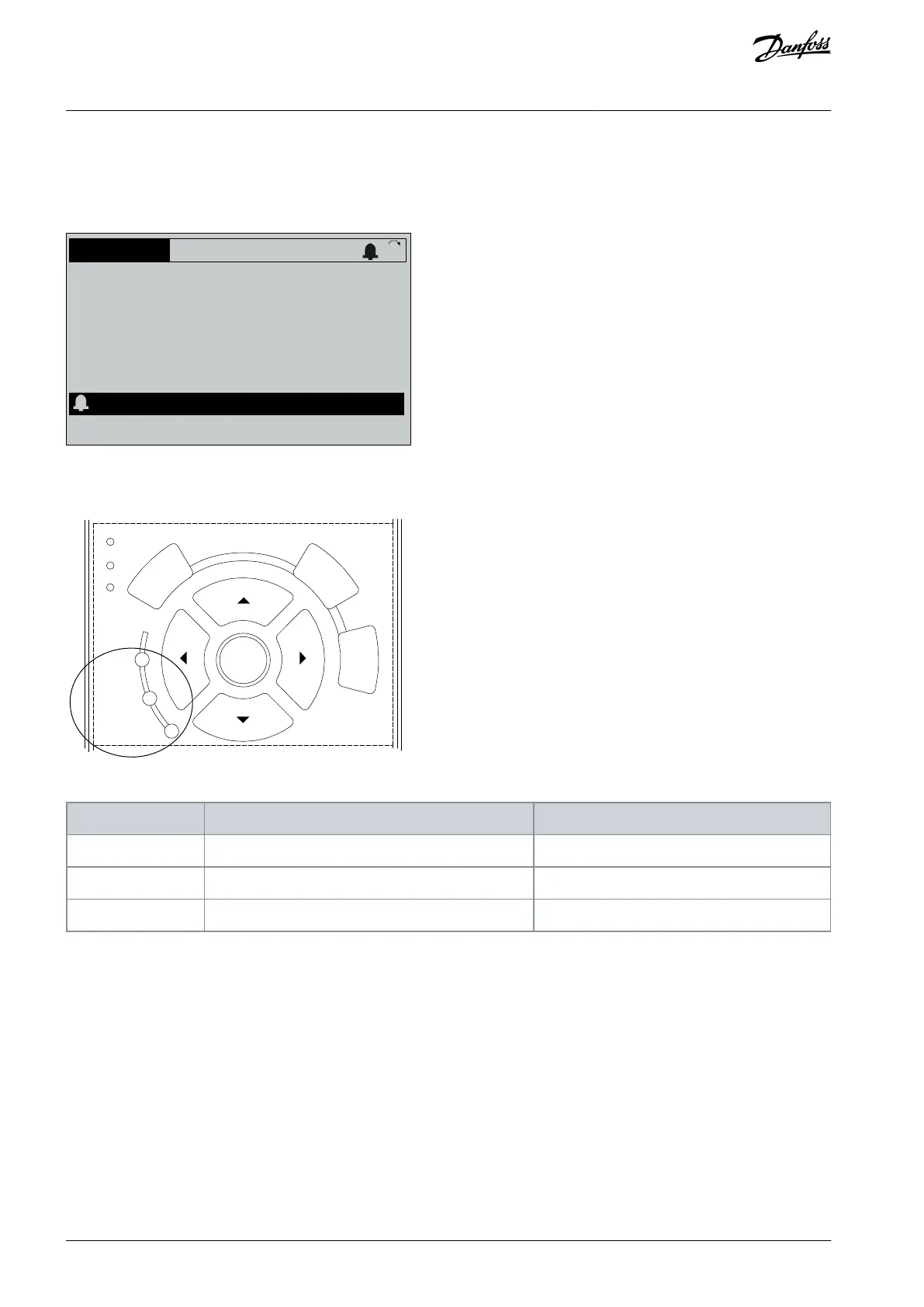
0.0Hz 0.000kW 0.00A
0.0Hz
0
Illustration 18: Alarm Example
In addition to the text and alarm code in the LCP there are 3 status indicator lights.
Info
OK
On
Alarm
Warn.
e30bb467.12
Illustration 19: Status Indicator Lights
7.4 Descriptions of Warnings and Alarms
Depending on settings, FC 301/302 is able to give warnings or trigger alarms. In the Programming Guide for VLT® AutomationDrive
FC 301/302, a full list of all warnings and alarms can be found. Below, an extract of most common alarms and warnings can be
found.
The following warning and alarm information defines each warning or alarm condition, provides the probable cause for the condi-
tion, and entails a remedy or troubleshooting procedure.
7.4.1 WARNING 1, 10 Volts Low
Cause
The control card voltage is less than 10 V from terminal 50. Remove some of the load from terminal 50, as the 10 V supply is overloa-
ded. Maximum 15 mA or minimum 590 Ω.
A short circuit in a connected potentiometer or incorrect wiring of the potentiometer can cause this condition.
AQ267037727118en-000101 / 130R030044 | Danfoss A/S © 2021.01
Maintenance, Diagnostics, and
Troubleshooting
VLT® AutomationDrive FC 301/FC 302
Operating Guide

 Loading...


