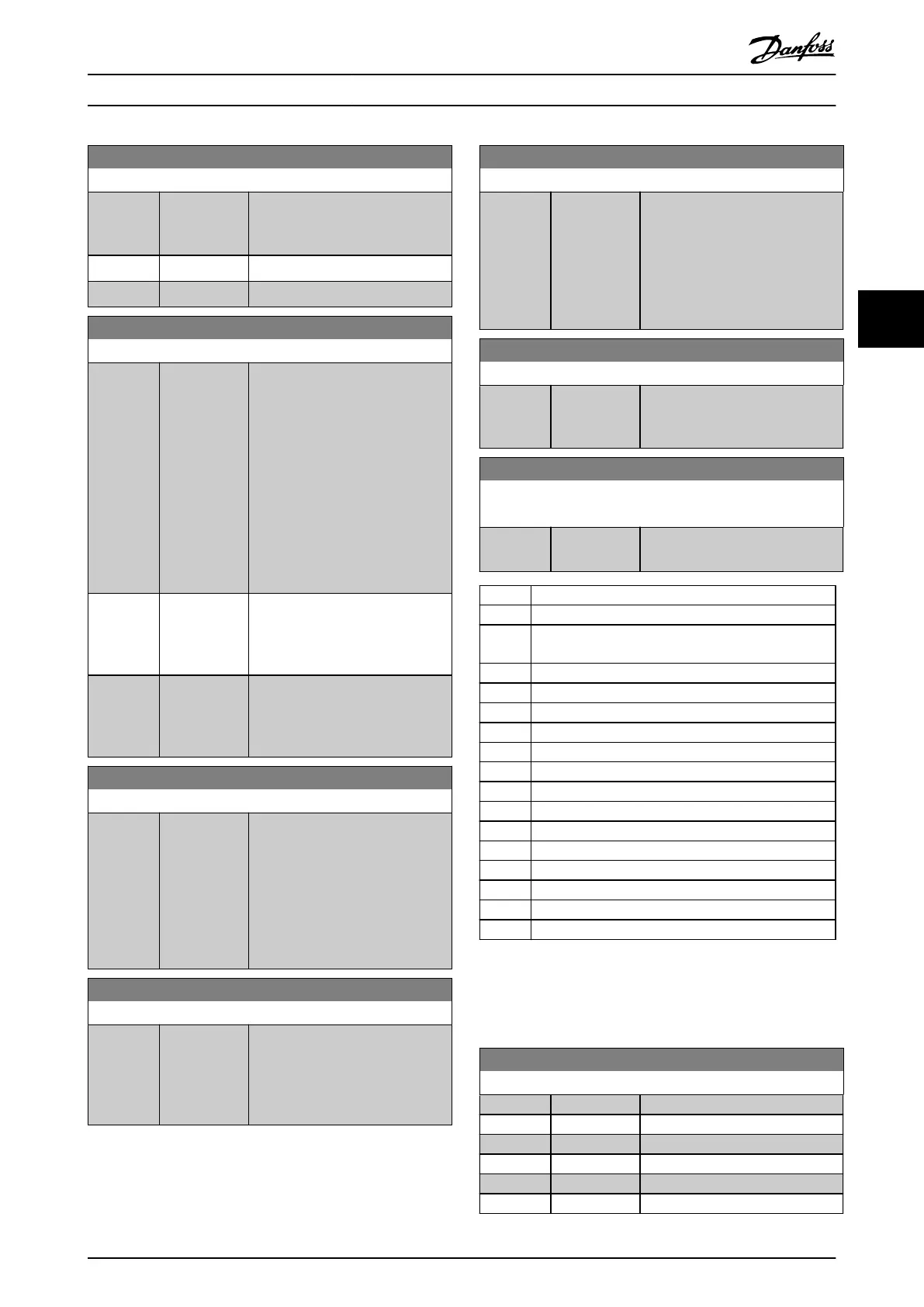
9-27 Parameter Edit
Option: Function:
Parameters can be edited via
PROFIBUS, the standard RS485
interface, or the LCP.
[0] Disabled Disable editing via PROFIBUS.
[1] * Enabled Enable editing via PROFIBUS.
9-28 Process Control
Option: Function:
Process control (setting of control
word, speed reference, and process
data) is possible via either
PROFINET or standard eldbus, but
not both simultaneously. Local
control is always possible via the
LCP. Control via process control is
possible via either terminals or
eldbus depending on the settings
in parameter 8-50 Coasting Select to
parameter 8-58 Prodrive OFF3
Select.
[0] Disable Disable process control via
PROFINET and enable process
control via standard eldbus or
PROFINET IO supervisor.
[1] * Enable cyclic
master
Enable process control via IO
controller and disable process
control via standard eldbus or
PROFINET IO supervisor.
9-44 Fault Message Counter
Range: Function:
0* [0 - 65535 ] This parameter shows the number
of error events stored in
parameter 9-45 Fault Code and
parameter 9-47 Fault Number. The
maximum buer capacity is eight
error events. The buer and counter
are set to 0 upon reset or power-
up.
9-45 Fault Code
Range: Function:
0* [0 - 0 ] This buer contains the alarm word
for all alarms and warnings that
have occurred since last reset or
power-up. The maximum buer
capacity is 8 error events.
9-47 Fault Number
Range: Function:
0* [0 - 0 ] This buer contains the alarm
number (for example, 2 for live zero
error, 4 for mains phase loss) for all
alarms and warnings that have
occurred since last reset or power-
up. The maximum buer capacity is
8 error events.
9-52 Fault Situation Counter
Range: Function:
0* [0 - 1000 ] This parameter shows the number
of error events that have occurred
since last reset or power-up.
9-53 Probus Warning Word
Read only
Range: Function:
0* [0 - 65535 ] This parameter shows PROFINET
communication warnings.
Bit Condition when bit is active
0 Connection with IO controller is not OK.
1
Reserved for status of connection with second IO
controller.
2 Not used.
3 Clear data command received.
4 Actual value is not updated.
5 No link on both ports.
6 Not used.
7 Initializing of PROFINET is not OK.
8 Frequency converter is tripped.
9 Internal CAN error.
10 Wrong conguration data from IO controller.
11 Not used.
12 Internal error occurred.
13 Not congured.
14 Timeout active.
15 Warning 34 active.
Table 4.17 PROFINET Communication Warnings
This parameter shows the actual PROFIBUS baud rate. The
PROFIBUS master automatically sets the baud rate.
9-63 Actual Baud Rate
Option: Function:
[0] 9,6 kbit/s
[1] 19,2 kbit/s
[2] 93,75 kbit/s
[3] 187,5 kbit/s
[4] 500 kbit/s
[6] 1500 kbit/s
Parameter Descriptions Programming Guide
MG06J202 Danfoss A/S © 03/2019 All rights reserved. 109
4 4
 Loading...


