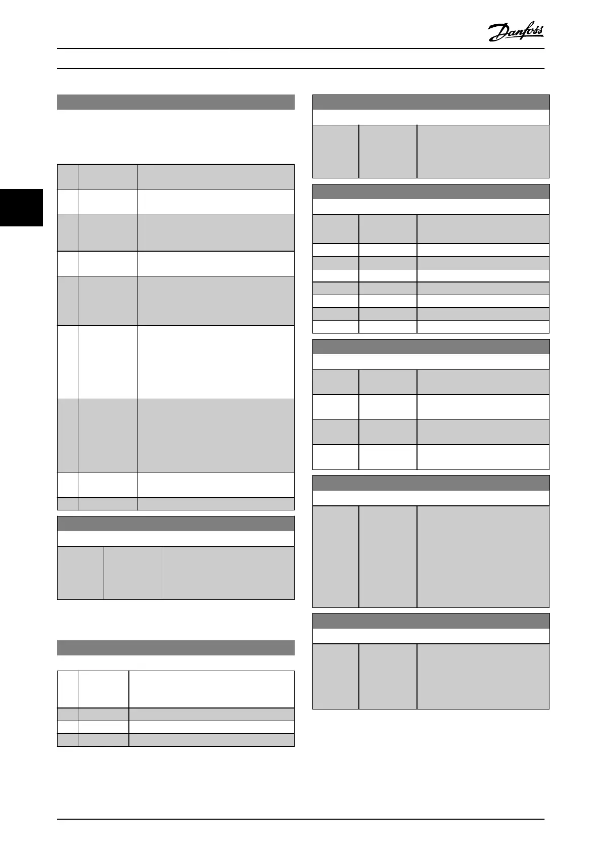
8-14 Congurable Control Word CTW
This is an array parameter with 16 elements, 1 element for each
bit in range 0–15. Each of the bits can be congured to any of
the following options.
Option: Function:
This parameter is not valid in software
versions before 4.93.
[0] None The frequency converter ignores the
information in this bit.
[1] * Prole default The functionality of the bit depends on
the selection in parameter 8-10 Control
Word Prole.
[2] CTW Valid,
active low
If set to 1, the frequency converter ignores
the remaining bits of the control word.
[4] PID error
inverse
Inverts the resulting error from the process
PID controller. Available only if
parameter 1-00 Conguration Mode is set to
[7] Extended PID Speed OL.
[5] PID reset I part Resets the I-part of the process PID
controller. Equivalent to
parameter 7-40 Process PID I-part Reset.
Available only if parameter 1-00 Congu-
ration Mode is set to [7] Extended PID
Speed OL.
[6] PID enable Enables the extended process PID
controller. Equivalent to
parameter 7-50 Process PID Extended PID.
Available only if parameter 1-00 Congu-
ration Mode is set to [7] Extended PID
Speed OL.
[7] External
Interlock
[66] Sleep Mode
8-19 Product Code
Range: Function:
Size
related*
[0 -
2147483647]
Select 0 to read out the actual
eldbus product code according to
the mounted eldbus option. Select
1 to read out the actual vendor ID.
4.9.3 8-3* FC Port Settings
8-30 Protocol
Option: Function:
Select the protocol to be used. Changing
protocol is not eective until after powering
o the frequency converter.
[0] * FC
[1] FC MC
[2] Modbus RTU
8-31 Address
Range: Function:
1* [ 1 - 247 ] Enter the address for the frequency
converter (standard) port.
Valid range: Depends on selected
protocol.
8-32 FC Port Baud Rate
Option: Function:
[0] 2400 Baud Baud rate selection for the FC
(standard) port.
[1] 4800 Baud
[2] 9600 Baud
[3] 19200 Baud
[4] 38400 Baud
[5] 57600 Baud
[6] 76800 Baud
[7] 115200 Baud
8-33 Parity / Stop Bits
Option: Function:
[0] * Even Parity, 1
Stop Bit
[1] Odd Parity, 1
Stop Bit
[2] No Parity, 1
Stop Bit
[3] No Parity, 2
Stop Bits
8-34 Estimated cycle time
Range: Function:
0 ms* [0 - 1000000
ms]
In noisy environments, the interface
may be blocked due to overload or
bad frames. This parameter species
the time between 2 consecutive
frames on the network. If the
interface does not detect valid
frames in that time, it ushes the
receive buer.
8-35 Minimum Response Delay
Range: Function:
10 ms* [ 1 - 10000
ms]
Specify the minimum delay time
between receiving a request and
transmitting a response. This is
used for overcoming modem
turnaround delays.
Parameter Descriptions VLT® AutomationDrive FC 361
96 Danfoss A/S © 03/2019 All rights reserved. MG06J202
44
 Loading...


