EasyManuals Logo
Home>Danfoss>DC Drives>VLT Flow Drive FC 111

Danfoss VLT Flow Drive FC 111 Design Guide

Danfoss VLT Flow Drive FC 111
148 pages
To Next Page IconTo Next Page
To Previous Page IconTo Previous Page
Page #102 background imageLoading...
Page #102 background image
1.
2.
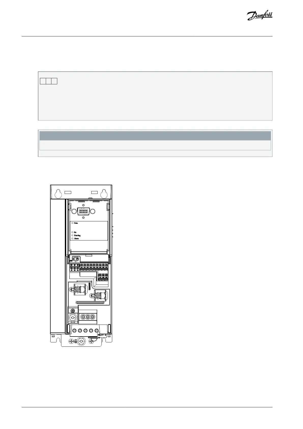
8.1.2 Connecting the Drive to the RS485 Network
Procedure
Connect signal wires to terminal 68 (P+) and terminal 69 (N-) on the main control board of the drive.
61 68 69
N
P
C
OMM. GND
e30bb795.10
Illustration 64: Network Connection
Connect the cable shield to the cable clamps.
N O T I C E
To reduce noise between conductors, use shielded, twisted-pair cables.
8.1.3 Hardware Set-up
To terminate the RS485 bus, use the terminator switch on the main control board of the drive.
e30bg049.10
Illustration 65: Terminator Switch Factory Setting
The factory setting for the switch is OFF.
AJ363928382091en-000101 / 130R0983102 | Danfoss A/S © 2021.04
RS485 Installation and Set-up
VLT® Flow Drive FC 111
Design Guide

Table of Contents

Other manuals for Danfoss VLT Flow Drive FC 111

Questions and Answers:

Question and Answer IconNeed help?

Do you have a question about the Danfoss VLT Flow Drive FC 111 and is the answer not in the manual?

Danfoss VLT Flow Drive FC 111 Specifications

General IconGeneral
BrandDanfoss
ModelVLT Flow Drive FC 111
CategoryDC Drives
LanguageEnglish

Related product manuals