implementation, the low-order byte of the field is appended first, followed by the high-order byte. The CRC high-order byte is the
last byte sent in the telegram.
8.8.8 Coil Register Addressing
8.8.8.1 Introduction
In Modbus, all data is organized in coils and holding registers. Coils hold a single bit, whereas holding registers hold a 2 byte word
(that is 16 bits). All data addresses in Modbus telegrams are referenced to 0. The 1
st
occurrence of a data item is addressed as item
number 0. For example: The coil known as coil 1 in a programmable controller is addressed as coil 0000 in the data address field of a
Modbus telegram. Coil 127 decimal is addressed as coil 007Ehex (126 decimal).
Holding register 40001 is addressed as register 0000 in the data address field of the telegram. The function code field already speci-
fies a holding register operation. Therefore, the 4XXXX reference is implicit. Holding register 40108 is addressed as register 006Bhex
(107 decimal).
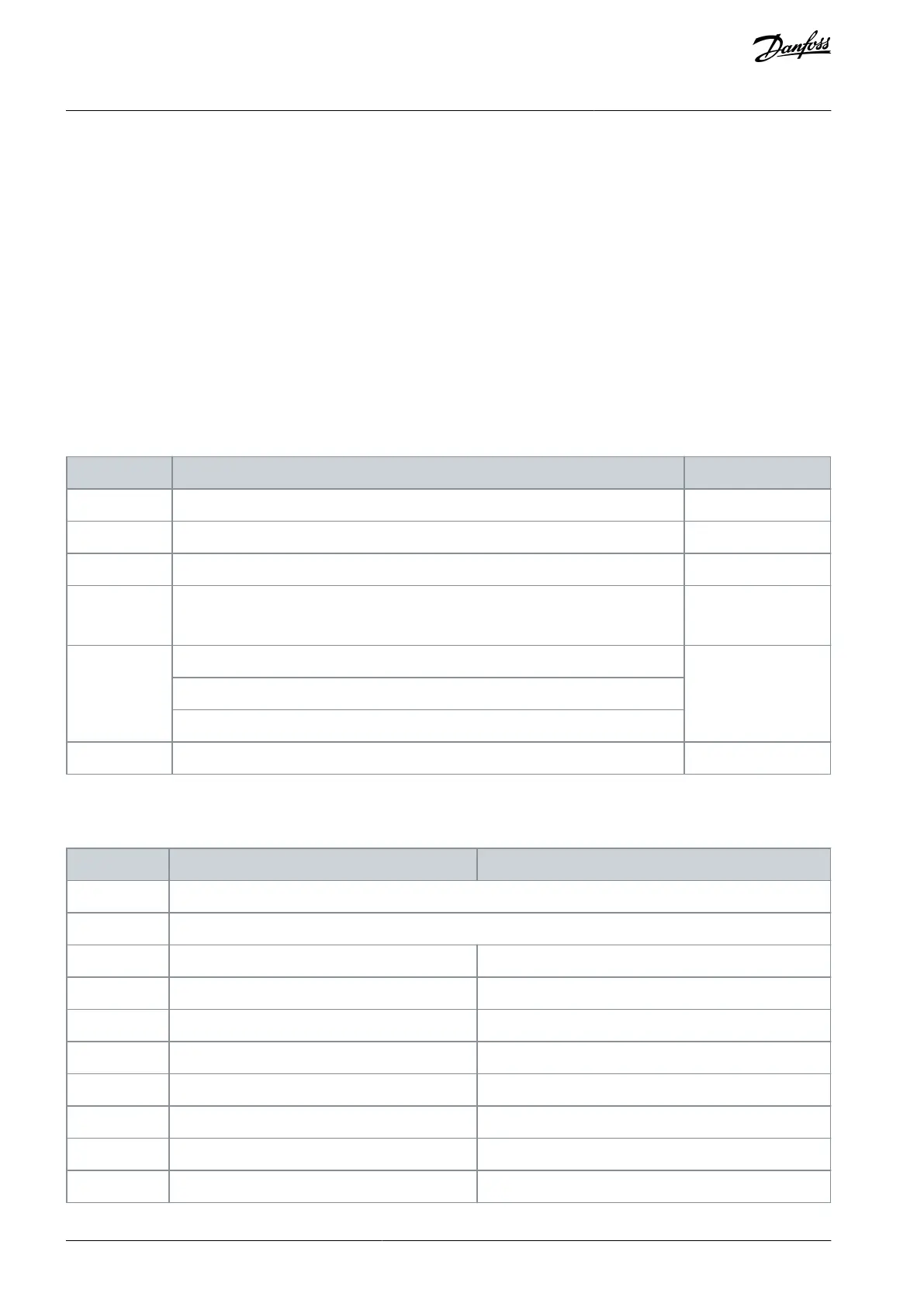
8.8.8.2 Coil Register
Table 63: Coil Register
Drive speed or setpoint reference range 0x0– 0xFFFF (-200% ... ~200%).
Open-loop mode: Drive output frequency.
Closed-loop mode: Drive feedback signal.
Parameter write control (master to follower).
0 = Parameter changes are written to the RAM of the drive.
1 = Parameter changes are written to the RAM and EEPROM of the drive.
8.8.8.3 Drive Control Word (FC Profile)
Table 64: Drive Control Word (FC Profile)
AJ363928382091en-000101 / 130R0983114 | Danfoss A/S © 2021.04
RS485 Installation and Set-up
VLT® Flow Drive FC 111
Design Guide
 Loading...


