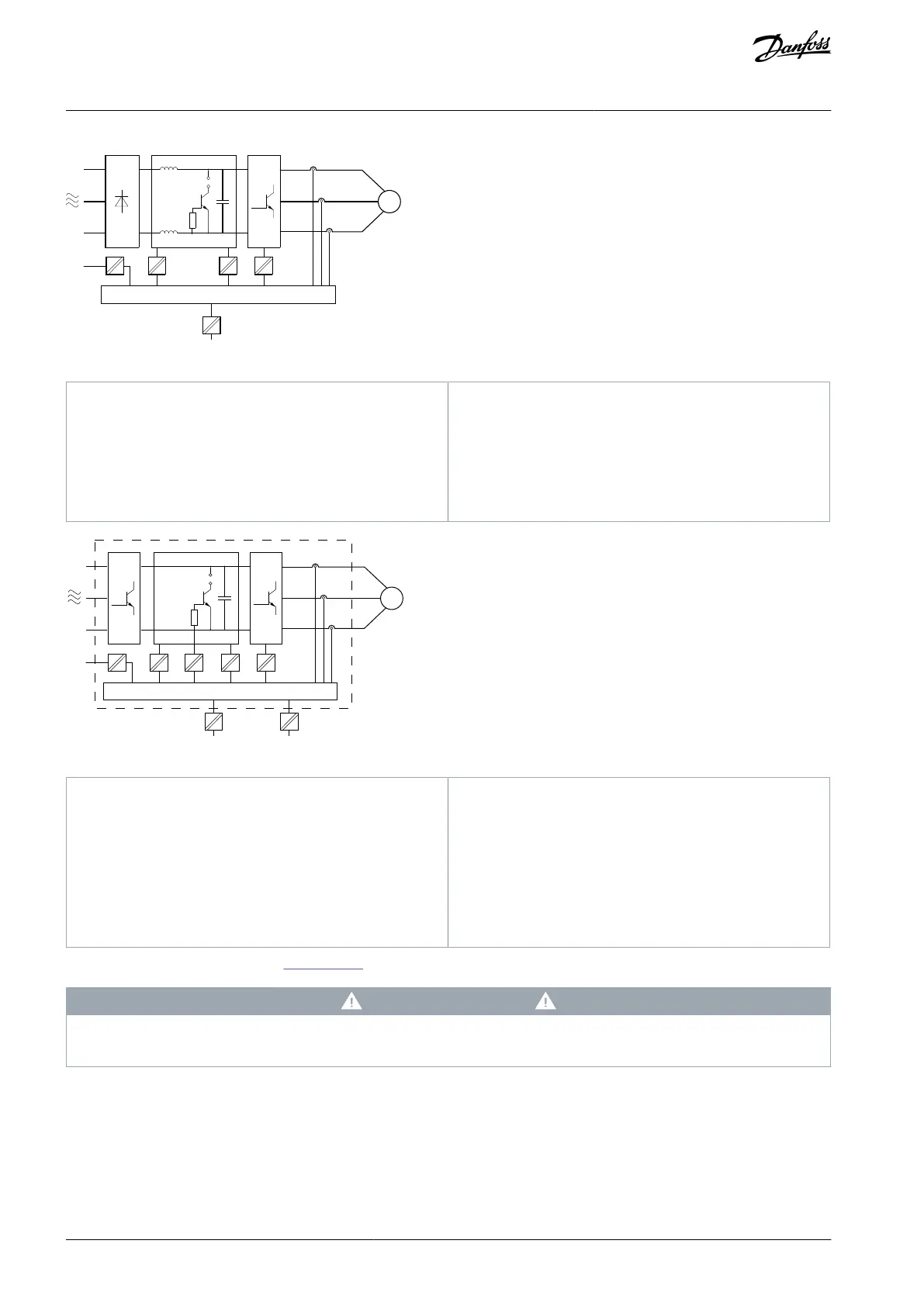
Illustration 25: Galvanic Isolation 30–90 kW (40–120 hp)
Supply (SMPS) including signal isolation of UDC, in-
dicating the intermediate current voltage
Gate drive that runs the IGBTs (trigger transformers/
optocouplers)
Internal soft-charge, RFI, and temperature measure-
ment circuits
Illustration 26: Galvanic Isolation 110–315 kW (150–450 hp)
Galvanic isolation for the RS485 standard bus inter-
face
Supply (SMPS) including signal isolation of V DC, in-
dicating the intermediate current voltage
Galvanic isolation for the 24 V back-up option
Opto-coupler, brake module (optional)
Internal inrush, RFI, and temperature measurement
circuits
The functional galvanic isolation (see Illustration 24) is for the RS485 standard bus interface.
C A U T I O N
INSTALLATION AT HIGH ALTITUDE
At altitudes above 2000 m (6500 ft), contact Danfoss regarding PELV.
3.6 Ground Leakage Current
Follow national and local codes regarding protective earthing of equipment where leakage current exceeds 3.5 mA.
Drive technology implies high frequency switching at high power. This generates a leakage current in the ground connection.
The ground leakage current is made up of several contributions and depends on various system configurations, including:
AJ363928382091en-000101 / 130R098338 | Danfoss A/S © 2021.04
Product Overview
VLT® Flow Drive FC 111
Design Guide
 Loading...


