EasyManuals Logo

Danfoss VLT Flow Drive FC 111 Design Guide

Danfoss VLT Flow Drive FC 111
148 pages
To Next Page IconTo Next Page
To Previous Page IconTo Previous Page
Page #70 background imageLoading...
Page #70 background image
e30bu776.10
1
2
3
4
5
6
7
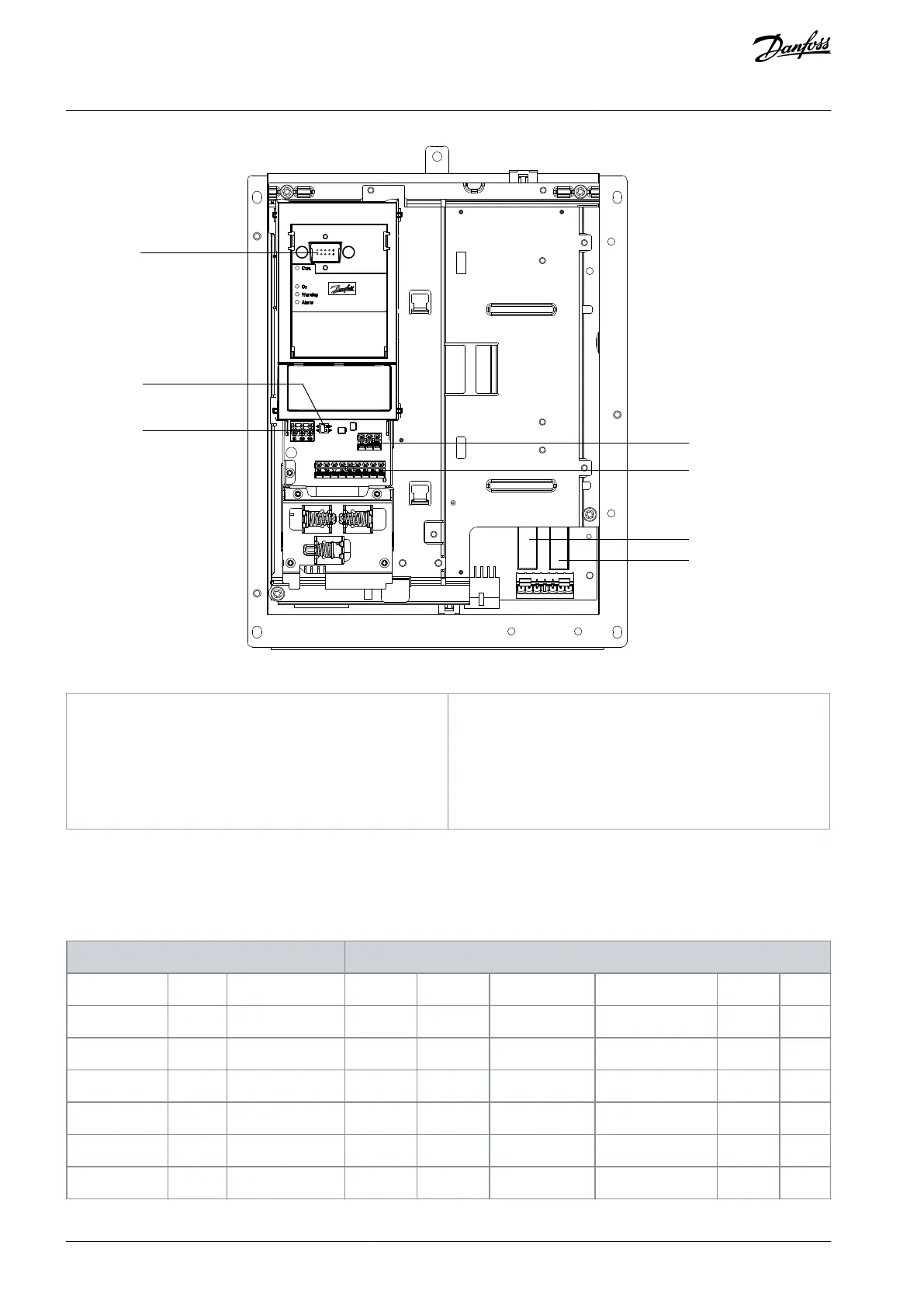
Illustration 53: View of Control Shelf in H13–H14
1
LCP connector
2
RS485 termination switch
3
RS485 fieldbus connector
4
Analog I/O connector
5
Digital I/O and 24 V supply
6
Relay 1 on power card
7
Relay 2 on power card
6.6 Fastener Tightening Torques
Apply the correct torque when tightening fasteners in the locations that are listed in the following tables. Too low or too high tor-
que when fastening an electrical connection results in a bad electrical connection. To ensure correct torque, use a torque wrench.
Table 36: Tightening Torques for Enclosure Sizes H1–H8, 3x380–480 V
Power [kW (hp)]
Torque [Nm (in-lb)]
Enclosure size
IP class
3x380–480 V
Mains
Motor
DC connection
Control terminals
Ground
Relay
H1
IP20
0.37–1.5 (0.5–2.0)
0.8 (7)
0.8 (7)
0.8 (7)
0.5 (4)
0.8 (7)
0.5 (4)
H2
IP20
2.2–4.0 (3.0–5.4)
0.8 (7)
0.8 (7)
0.8 (7)
0.5 (4)
0.8 (7)
0.5 (4)
H3
IP20
5.5–7.5 (7.5–10)
0.8 (7)
0.8 (7)
0.8 (7)
0.5 (4)
0.8 (7)
0.5 (4)
H4
IP20
11–15 (15–20)
1.2 (11)
1.2 (11)
1.2 (11)
0.5 (4)
0.8 (7)
0.5 (4)
H5
IP20
18.5–22 (25–30)
1.2 (11)
1.2 (11)
1.2 (11)
0.5 (4)
0.8 (7)
0.5 (4)
H6
IP20
30–45 (40–60)
4.5 (40)
4.5 (40)
0.5 (4)
3 (27)
0.5 (4)
AJ363928382091en-000101 / 130R098370 | Danfoss A/S © 2021.04
Electrical Installation
Considerations
VLT® Flow Drive FC 111
Design Guide

Table of Contents

Other manuals for Danfoss VLT Flow Drive FC 111

Questions and Answers:

Question and Answer IconNeed help?

Do you have a question about the Danfoss VLT Flow Drive FC 111 and is the answer not in the manual?

Danfoss VLT Flow Drive FC 111 Specifications

General IconGeneral
BrandDanfoss
ModelVLT Flow Drive FC 111
CategoryDC Drives
LanguageEnglish

Related product manuals