•
•
•
•
•
-
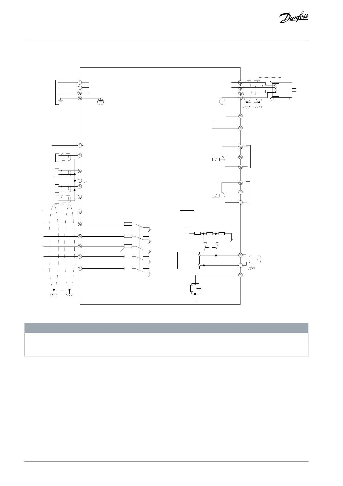
6.2 Electrical Wiring
+10 V DC
0-10 V DC-
0-10 V DC-
50 (+10 V OUT)
54 (A IN)
53 (A IN)
55 (COM A IN/OUT)
42 0/4-20 mA A OUT / D OUT
45 0/4-20 mA A OUT / D OUT
18 (D IN)
19 (D IN)
27 (D IN/OUT)
29 (D IN/OUT)
12 (+24 V OUT)
24 V (NPN)
20 (COM D IN)
O V (PNP)
24 V (NPN)
O V (PNP)
24 V (NPN)
O V (PNP)
24 V (NPN)
O V (PNP)
Bus ter.
Bus ter.
RS485
Interface
RS485
(N RS485) 69
(P RS485) 68
(Com RS485 ) 61
(PNP)-Source
(NPN)-Sink
ON=Terminated
OFF=Unterminated
ON
1 2
240 V AC 3 A
Not present on all power sizes
Do not connect shield to 61
01
02
03
relay 1
relay 2
UDC+
UDC-
Motor
U
V
W
e30bd467.12
06
05
04
240 V AC 3 A
Illustration 46: Basic Wiring Schematic Drawing
N O T I C E
There is no access to UDC- and UDC+ on the following units:
IP20, 380–480 V, 30–315 kW (40–450 hp)
6.3 EMC-compliant Electrical Installation
To ensure EMC-correct electrical installation, observe the following:
Use only shielded/armored motor cables and shielded/armored control cables.
Ground the shield at both ends.
Avoid installation with twisted shield ends (pigtails), because it reduces the shielding effect at high frequencies. Use the cable
clamps provided.
Ensure the same potential between the drive and the ground potential of PLC.
Use star washers and galvanically conductive installation plates.
AJ363928382091en-000101 / 130R098364 | Danfoss A/S © 2021.04
Electrical Installation
Considerations
VLT® Flow Drive FC 111
Design Guide
 Loading...


