N O T I C E
To define how bit 13 gates with the corresponding function on the digital inputs, use parameter 8-55 Set-up Select.
8.11.2.14 Bit 15, Reverse
Bit 15 = 0: No reversing.
Bit 15 = 1: Reversing. In the default setting, reversing is set to [0] Digital input in parameter 8-54 Reversing Select. Bit 15 causes revers-
ing only when [1] Bus, [2] Logic AND or [3] Logic OR is selected.
8.11.3 Status Word According to FC Profile (STW)
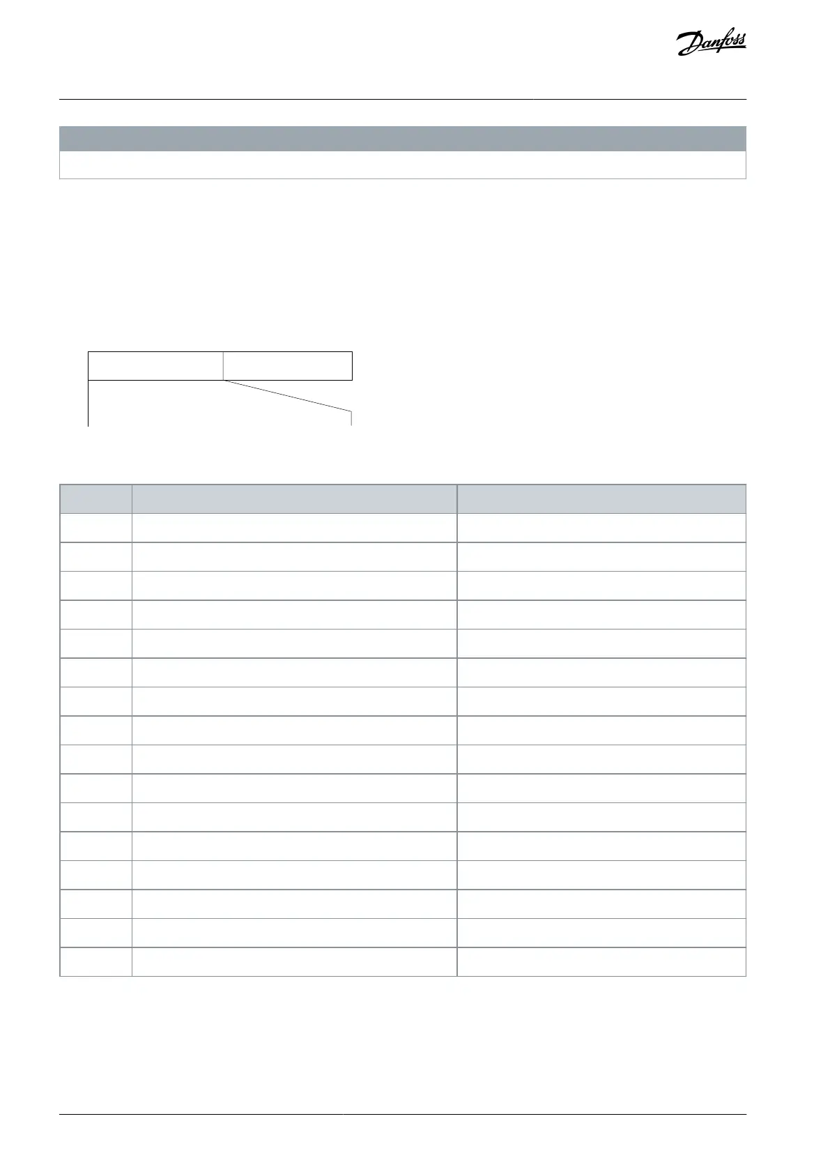
Set parameter 8-30 Protocol to [0] FC.
Output freq.STW
Follower-master
e30ba273.11
15 14 13 12 11 10 9 8 7 6 5 4 3 2 1 0
Bit
no.:
Illustration 79: Status Word
Table 87: Status Word According to FC Profile
8.11.4 Explanation of Each Status Bit
8.11.4.1 Bit 00, Control Not Ready/Ready
Bit 00=0: The drive trips.
Bit 00=1: The drive controls are ready but the power component does not necessarily receive any supply (if there is 24 V external
supply to controls).
AJ363928382091en-000101 / 130R0983128 | Danfoss A/S © 2021.04
RS485 Installation and Set-up
VLT® Flow Drive FC 111
Design Guide
 Loading...


