8.11.2 Explanation of Each Control Bit
8.11.2.1 Bits 00/01
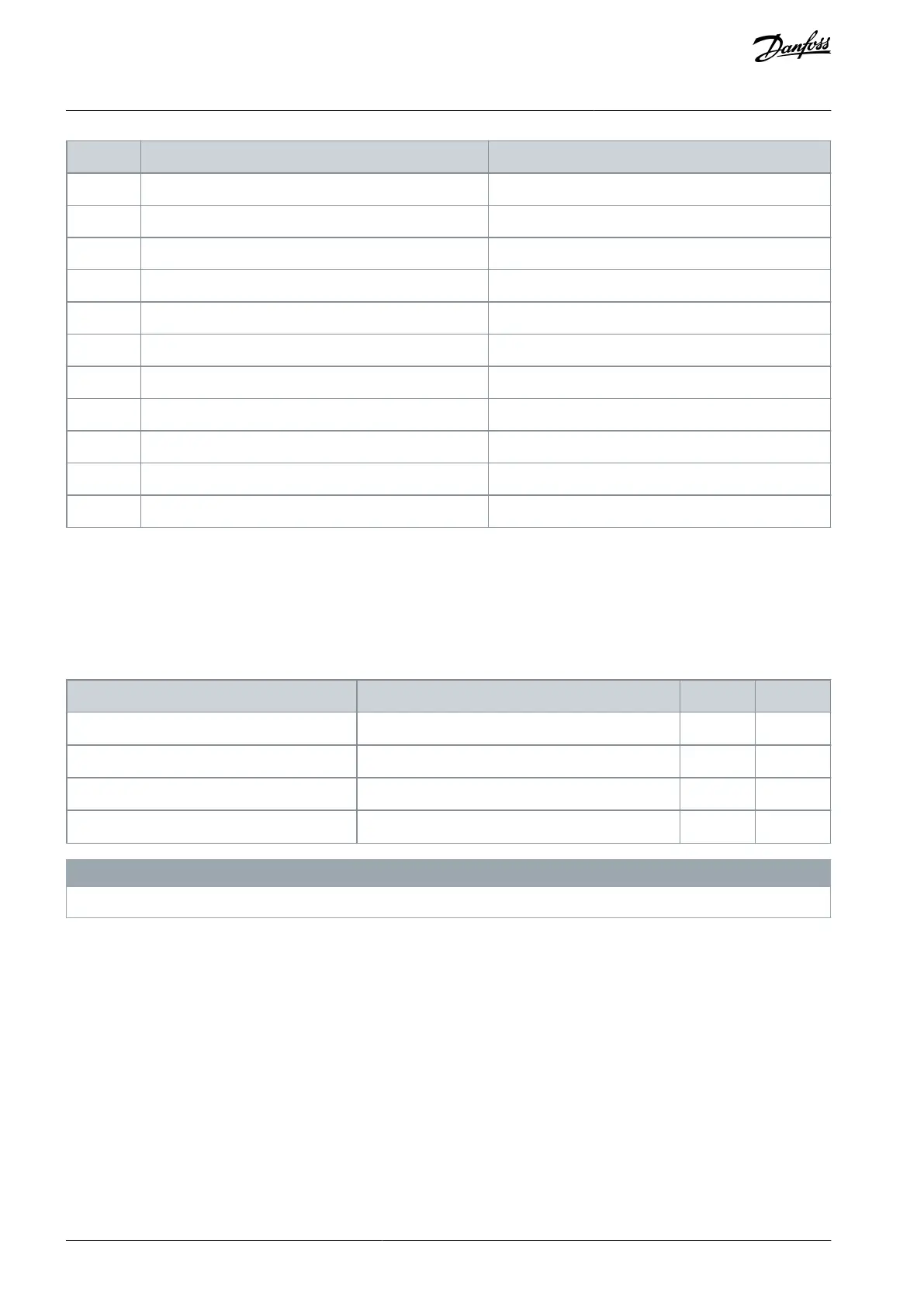
Bits 00 and 01 are used to select among the 4 reference values, which are preprogrammed in parameter 3-10 Preset Reference ac-
cording to the following table.
Table 85: Control Bits
Programmed reference value
Parameter 3-10 Preset Reference [0]
Parameter 3-10 Preset Reference [1]
Parameter 3-10 Preset Reference [2]
Parameter 3-10 Preset Reference [3]
N O T I C E
In parameter 8-56 Preset Reference Select, define how bit 00/01 gates with the corresponding function on the digital inputs.
8.11.2.2 Bit 02, DC Brake
Bit 02 = 0: Leads to DC braking and stop. Set braking current and duration in parameter 2-01 DC Brake Current and parameter 2-02 DC
Braking Time.
Bit 02 = 1: Leads to ramping.
8.11.2.3 Bit 03, Coasting
Bit 03 = 0: The drive immediately releases the motor (the output transistors are shut off), and it coasts to a standstill.
Bit 03 = 1: If the other starting conditions are met, the drive starts the motor.
In parameter 8-50 Coasting Select, define how bit 03 gates with the corresponding function on a digital input.
8.11.2.4 Bit 04, Quick Stop
Bit 04 = 0: Makes the motor speed ramp down to stop (set in parameter 3-81 Quick Stop Ramp Time).
AJ363928382091en-000101 / 130R0983126 | Danfoss A/S © 2021.04
RS485 Installation and Set-up
VLT® Flow Drive FC 111
Design Guide
 Loading...


