EasyManuals Logo
Home>Danfoss>DC Drives>VLT Flow Drive FC 111

Danfoss VLT Flow Drive FC 111 Design Guide

Danfoss VLT Flow Drive FC 111
148 pages
To Next Page IconTo Next Page
To Previous Page IconTo Previous Page
Page #44 background imageLoading...
Page #44 background image
Set parameter 1-90 Motor Thermal Protection to [2] Thermistor Trip.
Set parameter 1-93 Thermistor Source to [1] Analog Input 53.
N O T I C E
Do not set Analog Input 54 as reference source.
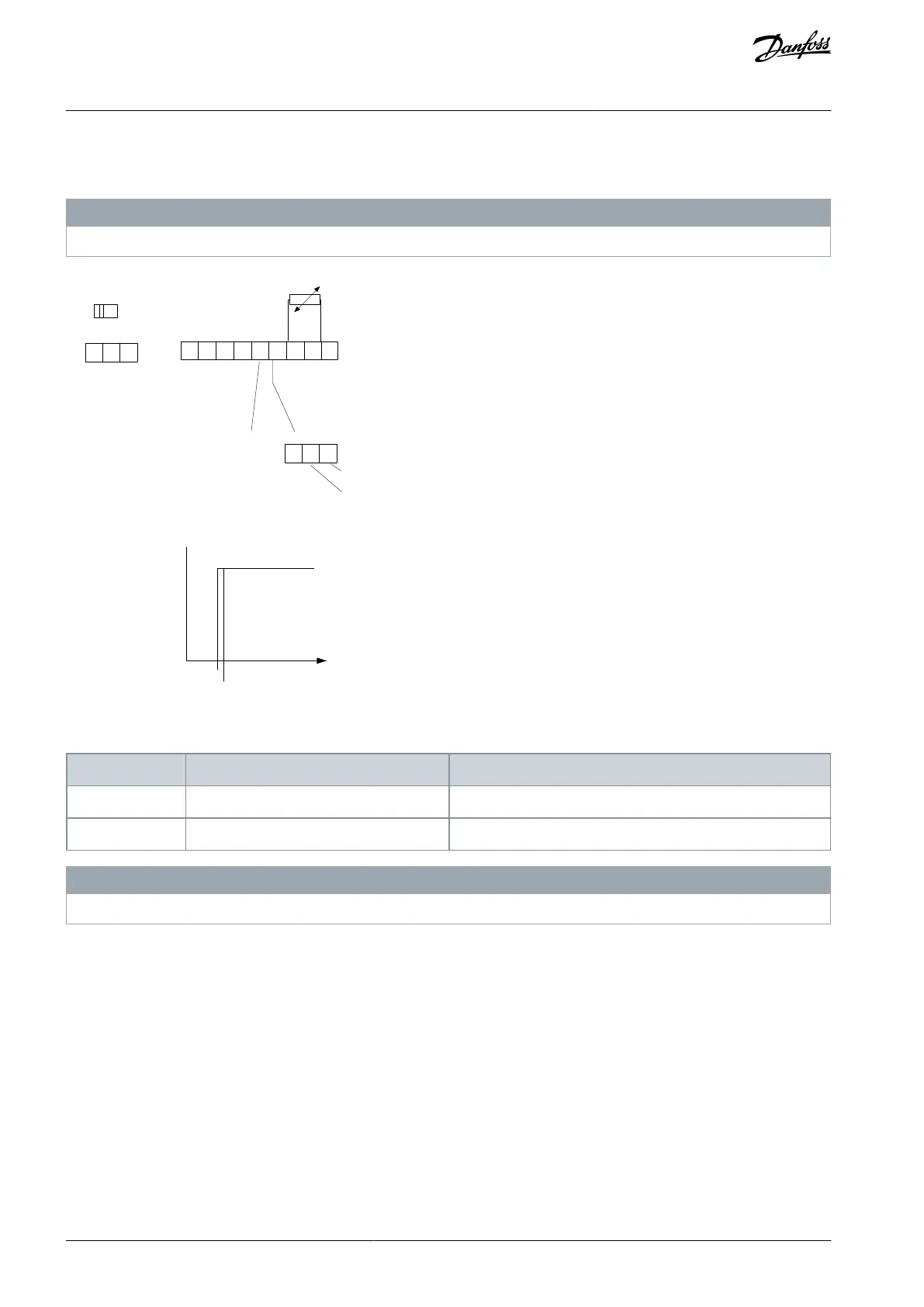
18
19
12 20 55
27 29 42 45 50 53 54
DIGI IN
DIGI IN
DIGI IN
DIGI IN
61
68
69
N
P
C OMM. GND
+24V
0/4-20mA A OUT / DIG OUT 0/4-20mA A OUT / DIG OUT
C OM A IN
C OM DIG IN
10V/20mA IN
10V/20mA IN
10V OUT
BUS TER.
OFF
ON
e30bb897.10
R
<3.0 k
Ω
>2.9k Ω
OFF
ON
Illustration 34: Analog Input/10 V Power Supply
Table 19: Supply Voltage
Input
Supply voltage [V]
Threshold cutout values [Ω]
Digital
10
<8002.9 k
Analog
10
<8002.9 k
N O T I C E
Make sure that the selected supply voltage follows the specification of the used thermistor element.
ETR is activated in parameter 1-90 Motor Thermal Protection.
AJ363928382091en-000101 / 130R098344 | Danfoss A/S © 2021.04
Product Overview
VLT® Flow Drive FC 111
Design Guide

Table of Contents

Other manuals for Danfoss VLT Flow Drive FC 111

Questions and Answers:

Question and Answer IconNeed help?

Do you have a question about the Danfoss VLT Flow Drive FC 111 and is the answer not in the manual?

Danfoss VLT Flow Drive FC 111 Specifications

General IconGeneral
BrandDanfoss
ModelVLT Flow Drive FC 111
CategoryDC Drives
LanguageEnglish

Related product manuals