Make sure that the impedance from frequency converter to building ground is lower that the grounding impedance of the machine. This can be
difficult for pumps- Make a direct earth connection between the motor and load motor.
3. Apply conductive lubrication
4. Try to ensure the line voltage is balanced to ground. This can be difficult for IT, TT, TN-CS or Grounded leg systems
5. Use an insulated bearing as recommended by the motor manufacturer (note: Motors from reputable manufacturers will typically have these
fitted as standard in motors of this size)
If found to be necessary and after consultation with Danfoss:
6. Lower the IGBT switching frequency
7. Modify the inverter waveform, 60° AVM vs. SFAVM
8. Install a shaft grounding system or use an isolating coupling between motor and load
9. Use minimum speed settings if possible
10. Use a dU/dt or sinus filter
5.5 Installation of misc. connections
5.5.1 RS 485 Bus Connection
One or more frequency converters can be connected to a control (or
master) using the RS485 standardized interface. Terminal 68 is connec-
ted to the P signal (TX+, RX+), while terminal 69 is connected to the N
signal (TX-,RX-).
If more than one frequency converter is connected to a master, use par-
allel connections.
In order to avoid potential equalizing currents in the screen, earth the cable screen via terminal 61, which is connected to the frame via an RC-link.
Bus termination
The RS485 bus must be terminated by a resistor network at both ends. For this purpose, set switch S801 on the control card for "ON".
For more information, see the paragraph
Switches S201, S202, and S801
.
Communication protocol must be set to par. 8-30
Protocol
.
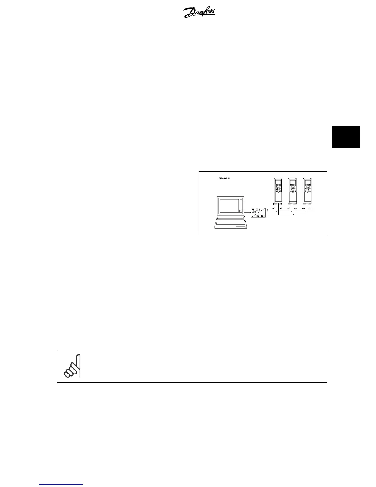
5.5.2 How to connect a PC to the frequency converter
To control or program the frequency converter from a PC, install the PC-based Configuration Tool MCT 10.
The PC is connected via a standard (host/device) USB cable, or via the RS-485 interface as shown in the VLT HVAC Drive
Design Guide, chapter How to
Install > Installation of misc. connections
.
NB!
The USB connection is galvanically isolated from the supply voltage (PELV) and other high-voltage terminals. The USB connection is
connected to protection earth on the frequency converter. Use only an isolated laptop as PC connection to the USB connector on the
frequency converter.
VLT
®
HVAC Drive Design Guide 5 How to Install
MG.11.B9.02 - VLT
®
is a registered Danfoss trademark
111
5

 Loading...


